3MAINTENANCE__O.pdf - 第148页
3.7 Unit Adjustment Only the person in charge of maintenance work should perform machine operations with the [ OPERATION ] switch set to the “ SET UP ” side . A WARNING o 3 一 58 QRO ^ - nm ACP 01 EIN 3 - 58
3.7
Unit
Adjustment
3.7
.
3
Camera
Position
Adjustment
When
the
[
CAMERA
POSITION
ADJUSTMENT
]
key
is
pressed
at
the
“
UNIT
ADJUSTMENT
”
display
,
the
following
display
appears
on
the
screen
.
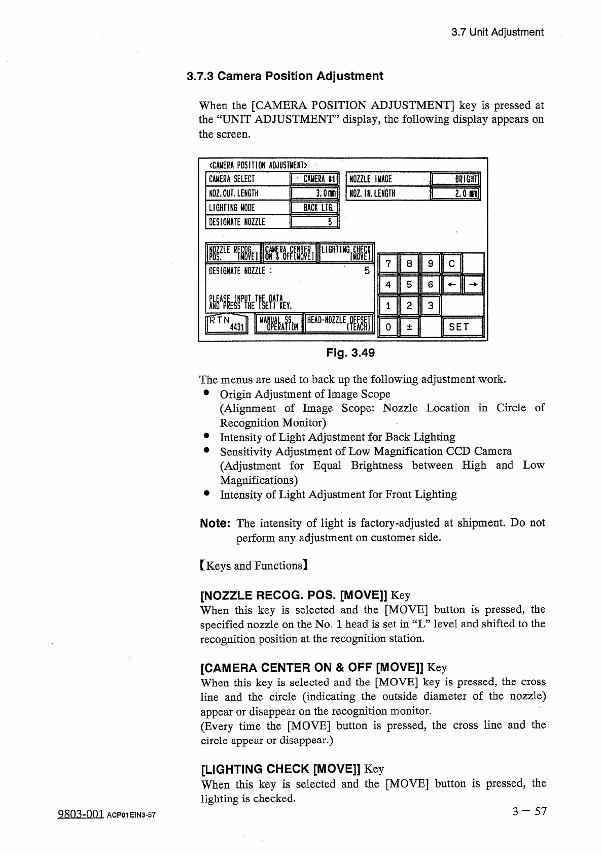
〈
CAMERA
POSITION
ADJUSTMENT
)
NOZZLE
IMACE
|
|
BRiGHTlI
NQZ
;
iN
.
LENGTH
~
CAMERA
SELECT
|
’
CAMERA
tl
NOZ
.
OUT
.
LENGTH
LIGHTING
MODE
BACK
LIG
.
DESIGNATE
NOZZLE
T
rEmii
[
^
»
MlF
11
lir
DESIGNATE
NOZZLE
:
5
L
8
9
C
4
5
6
m
晶
MV
2
3
0
±
SET
Fig
.
3
49
The
menus
are
used
to
back
up
the
following
adjustment
work
.
•
Origin
Adjustment
of
Image
Scope
(
Alignment
of
Image
Scope
:
Nozzle
Location
in
Circle
of
Recognition
Monitor
)
•
Intensity
of
Light
Adjustment
for
Back
Lighting
•
Sensitivity
Adjustment
of
Low
Magnification
CCD
Camera
(
Adjustment
for
Equal
Brightness
between
High
and
Low
Magnifications
)
•
Intensity
of
Light
Adjustment
for
Front
Lighting
Note
:
The
intensity
of
light
is
factory
-
adjusted
at
shipment
.
Do
not
perform
any
adjustment
on
customer
side
.
[
Keys
and
Functions
!
[
NOZZLE
RECOG
.
POS
.
[
MOVE
]]
Key
When
this
key
is
selected
and
the
[
MOVE
]
button
is
pressed
,
the
specified
nozzle
on
the
No
.
1
head
is
set
in
“
L
”
level
and
shifted
to
the
recognition
position
at
the
recognition
station
.
[
CAMERA
CENTER
ON
&
OFF
[
MOVE
]]
Key
When
this
key
is
selected
and
the
[
MOVE
]
key
is
pressed
,
the
cross
line
and
the
circle
(
indicating
the
outside
diameter
of
the
nozzle
)
appear
or
disappear
on
the
recognition
monitor
.
(
Every
time
the
[
MOVE
]
button
is
pressed
,
the
cross
line
and
the
circle
appear
or
disappear
.
)
[
LIGHTING
CHECK
[
MOVE
]
】
Key
When
this
key
is
selected
and
the
[
MOVE
]
button
is
pressed
,
the
lighting
is
checked
.
3
一
57
Q
8
m
-
om
ACP
01
EIN
3
-
57
3.7
Unit
Adjustment
Only
the
person
in
charge
of
maintenance
work
should
perform
machine
operations
with
the
[
OPERATION
]
switch
set
to
the
“
SET
UP
”
side
.
A
WARNING
o
3
一
58
QRO
^
-
nm
ACP
01
EIN
3
-
58
3.8
HDD
/
FDD
Operation
3.8
HDD
/
FDD
Operation
When
the
[
HDD
/
FDD
OPERATION
]
key
is
pressed
at
the
“
SPECIAL
SEL
.
”
display
,
the
following
display
appears
on
the
screen
.
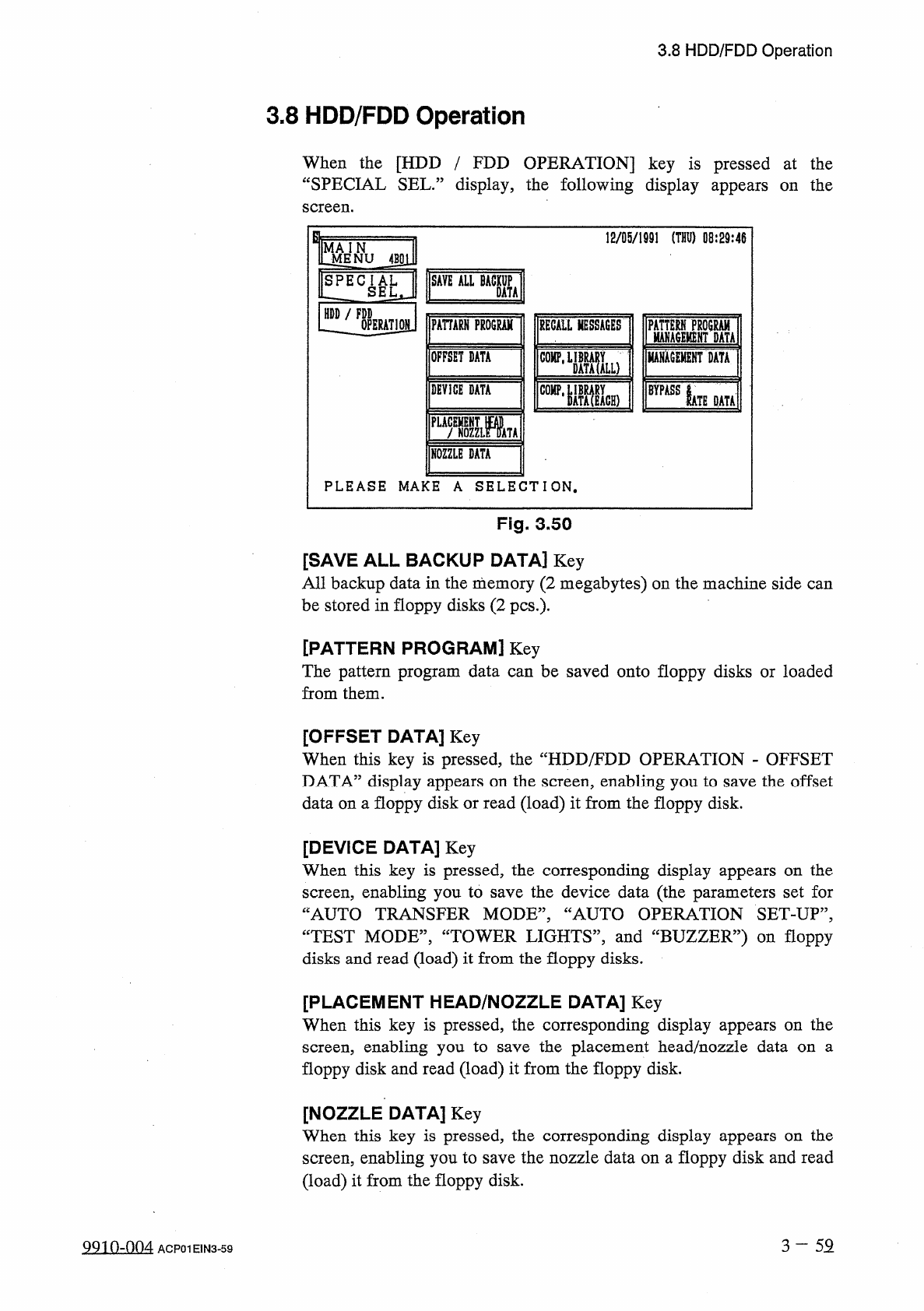
12
/
05
/
1991
(
THU
)
08
:
29
:
46
J
^
NU
4
BSl
]
SAVE
ALL
BACKUP
SPECIAL
LZ
SEL
,
DATA
HDD
/
FDD
PAHARH
PROGRAM
OPERATION
RECALL
MESSAGES
ISM
Mu
MAHACEMENT
DATA
OFFSET
DATA
COMP
,
DEVICE
DATA
BYPASS
IATE
DATA
PLACEMENT
m
f
NOZZLE
DATA
NOZZLE
DATA
PLEASE
MAKE
A
SELECTION
.
Fig
.
3.50
[
SAVE
ALL
BACKUP
DATA
]
Key
All
backup
data
in
the
memory
(
2
megabytes
)
on
the
machine
side
can
be
stored
in
floppy
disks
(
2
pcs
.
)
-
[
PATTERN
PROGRAM
]
Key
The
pattern
program
data
can
be
saved
onto
floppy
disks
or
loaded
from
them
.
[
OFFSET
DATA
]
Key
When
this
key
is
pressed
,
the
“
HDD
/
FDD
OPERATION
-
OFFSET
DATA
”
display
appears
on
the
screen
,
enabling
you
to
save
the
offset
data
on
a
floppy
disk
or
read
(
load
)
it
from
the
floppy
disk
.
[
DEVICE
DATA
]
Key
When
this
key
is
pressed
,
the
corresponding
display
appears
on
the
screen
,
enabling
you
to
save
the
device
data
(
the
parameters
set
for
“
AUTO
TRANSFER
MODE
,,
,
“
AUTO
OPERATION
SET
-
UP
”
,
CCTEST
MODE
”
,
“
TOWER
LIGHTS
,
,
,
and
“
BUZZER
”
)
on
floppy
disks
and
read
(
load
)
it
from
the
floppy
disks
.
[
PLACEMENT
HEAD
/
NOZZLE
DATA
]
Key
When
this
key
is
pressed
,
the
corresponding
display
appears
on
the
screen
,
enabling
you
to
floppy
disk
and
read
(
load
)
it
from
the
floppy
disk
.
the
placement
head
/
nozzle
data
on
a
save
[
NOZZLE
DATA
]
Key
When
this
key
is
pressed
,
the
corresponding
display
appears
on
the
screen
,
enabling
you
to
save
the
nozzle
data
on
a
floppy
disk
and
read
(
load
)
it
from
the
floppy
disk
.
3
-
52
QQin
-
nn
4
ACP
01
E
1
N
3
-
59