444CEMM1.pdf - 第72页
Page 1-10 7. Color touch panel 8. Board conveyor 4U4C-AA00 0306C0AA 6. T ransfer head 010DC0AA 9. T ape feeder table 150FC0AA Outline of Maintenance 1) Nozzle shaft support bearing 2) Air pass 1) T ouch panel face 1) Sup…
Page 1-9
REGULAR
MAINTENANCE
1
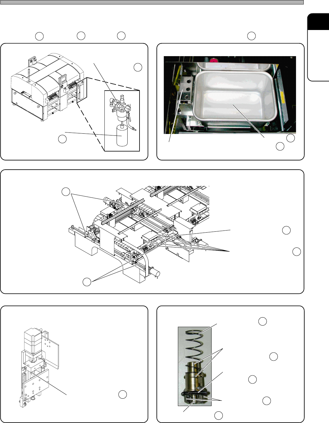
Outline of Maintenance
Regular check items are divided for the unit and illustrated. Make use of it for
reference.
= Check = Clean = Apply grease or lubricate (or exchange) = Exchange
2. NG parts discharge box
3. X-Y unit
444C-522P
010CC0AA
1. MR unit
4U4C-AB00 444C-424E
5. Nozzle holder (transfer head)
444C-515P
4. Z unit
011AC0AA
Ch
Cl Gr Ex
1) Pressure gauge
2) Water receiver
Ch
Cl
1) Tray
Cl
1) X-axis ball screw
2) X-axis linear bearing
Gr
Gr
Gr
3) Y-axis ball screw
Gr
4) Y-axis linear bearing
1) Z-axis ball screw Gr
1) Spring for nozzle cushion
2) Inner and outer
circumference
3) Spring for clamp arm
holder
4) Clamp arm
5) Taper face
Cl
Cl
444C-E-MMA01-A01-05
∗ This picture shows the one for CM201/202-DS.
∗ This illustration shows the one for CM202-DH.
∗ This illustration shows the one for CM202-DH.
∗ This illustration shows the one for CM202-DH.
2) Cleaning the Forced-Chip-Ejecting Unit
Cl
Cl
Cl
Cl
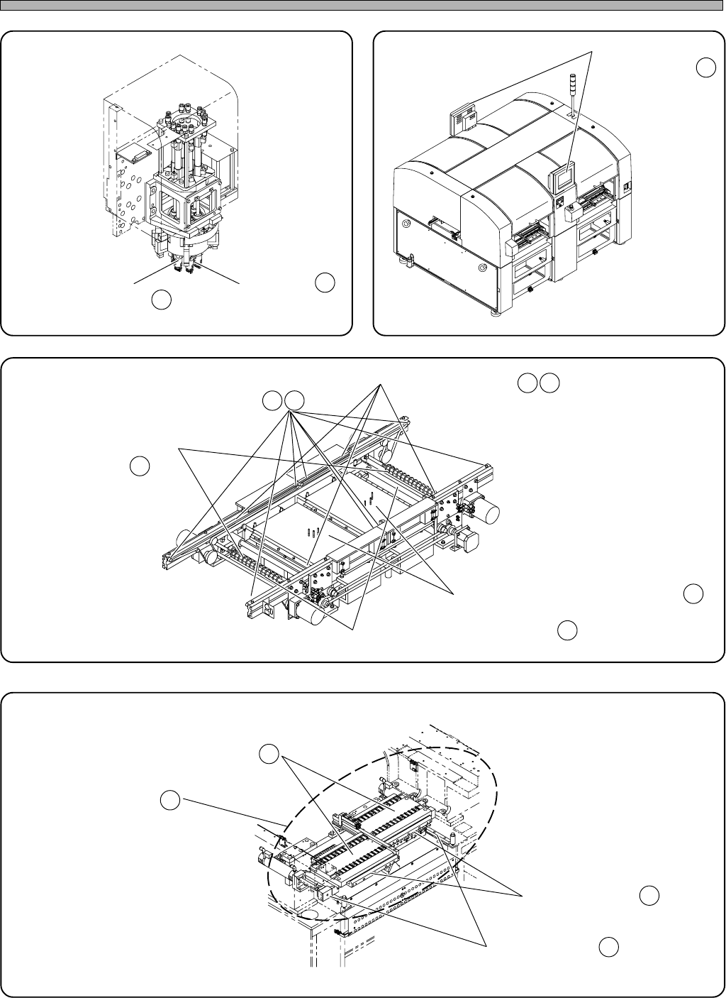
Page 1-10
7. Color touch panel
8. Board conveyor
4U4C-AA00
0306C0AA
6. Transfer head
010DC0AA
9. Tape feeder table
150FC0AA
Outline of Maintenance
1) Nozzle shaft
support bearing
2) Air pass
1) Touch panel face
1) Support pin batch exchange table
2) Board transfer belt
3) Roller
4) Width adjustment
ball screw
5) Width adjustment linear shaft
1) Tape feeder setting face
2) Surroundings
3) Projection bush
4) Linear bearing
Ch
Gr
Cl
Ch
Cl
Gr
Ex
Ch
Ex
Gr
444C-E-MMA01-A01-02
Cl
Gr
Ch
Cl
∗∗
∗∗
∗ This illustration shows the one for CM202-DH.
∗∗
∗∗
∗ This illustration shows the one for CM202-DH.
∗∗
∗∗
∗ This illustration shows the one for CM202-DH.
∗∗
∗∗
∗ This illustration shows the one for CM202-DH.
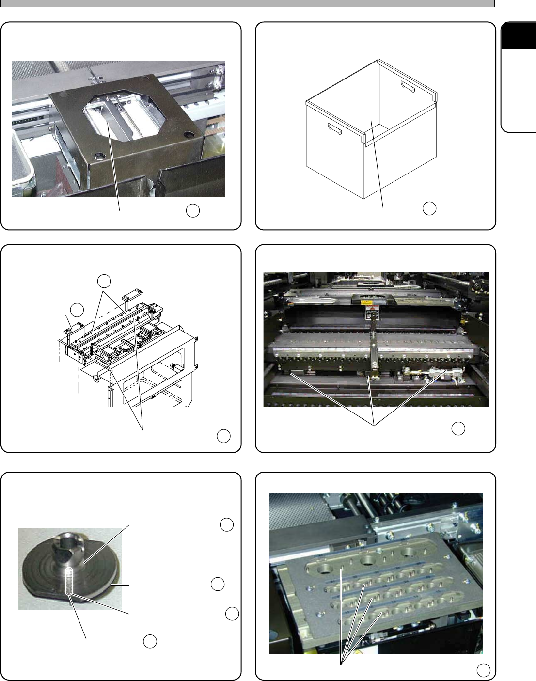
Page 1-11
REGULAR
MAINTENANCE
1
Outline of Maintenance
11. Used tape box (option)
100NC0AA
10. Line camera
444C-403P
13. Unit for double tape feeder (option)
444C-509P
12. Cutting unit (option)
CM201-D/DU and CM202-D/DU are options.
4U4C-010E
15. Nozzle changer (option)
444C-487P
14. Nozzle (option)
444C-513P
1) Cover glass
2) Fixed blade
2) Movable blade
1) Nozzle tip
2) Nozzle pickup hole
3) Nozzle taper face
4) Nozzle reflector
1) Inside
1) Linear bearing
1) Contact face of the nozzle reflector
Cl
Ex
Cl
Cl
Cl
Gr
Gr
Ex
Cl
Cl
Cl
444C-E-MMA01-A01-05
1) Left-side slide
block
∗∗
∗∗
∗ This picture shows the one for CM202-DH.