00198045-01_OM_BulkFeeder_X_EN.pdf - 第13页
SIPLACE BulkFeede r X / Operating Ma nual 05/2017 Edition 13 3.2 Cartridge Figure 3-2: Cartridge 1. Pickup plate (glass plate) w ith plate shutt er 2. Compone nt container wit h container shu tter (filled wit h component…
SIPLACE BulkFeeder X / Operating Manual 05/2017 Edition
12
3 SIPLACE BulkFeeder X – Functionality
The SIPLACE Bulkfeeder X [00141630-xx] consists of the following two main modules:
● SIPLACE BulkFeeder X Base Unit, item no: [00141600-xx]
● SIPLACE BulkFeeder X Cartridge, item no: [00141602-xx]
In the following, these modules are referred to as Base Unit and Cartridge respectively.
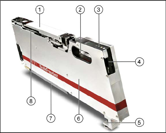
3.1 Base Unit
Figure 3-1: Base Unit
1. Cartridge 5. Mechanical mount
2. Handle 6. Camera, electronics, vibration unit
3. Control panel 7. Slide bars
4. Locking mechanism 8. RFID
The Base Unit of the SIPLACE BulkFeeder X looks similar to an SmartFeeder X and is just as easy
to install on the feeder table.
The Base Unit carries all active parts like optics, mechanics and electronics and occupies 3 tracks.
It has an EDIF (energy and data interface) on the 1
st
track and a second light conductor on the 3
rd
track. Additionally, it is equipped with a connector for the camera cable.
SIPLACE BulkFeeder X / Operating Manual 05/2017 Edition
13
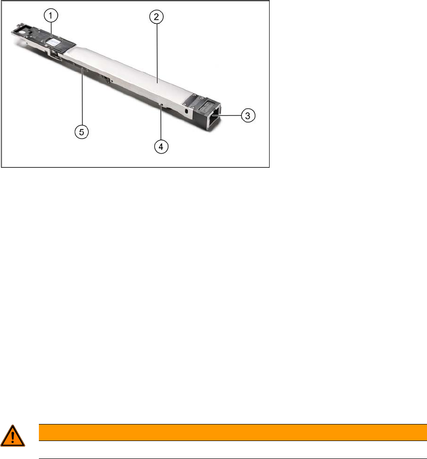
3.2 Cartridge
Figure 3-2: Cartridge
1. Pickup plate (glass plate) with plate shutter
2. Component container with container shutter (filled with components)
3. Refill connector
4. Clamping mechanism
5. RFID
The Cartridge SIPLACE BulkFeeder X consists of the pickup plate with pickup area and plate
shutter, the component container with container shutter and the filling funnel.
The Cartridge gets inserted on the Base Unit via a guide rail and can be easily replaced while the
feeder stays on the table. The Cartridge has a separate locking system and can be removed by
pressing the yellow button on the feeder for at least 1 second or under Manual Operations on the
station software GUI.
The components are picked up contactlessly from the glass plate. The surface of the glass plate is
structured to avoid that the components adhere.
WARNING
Do not touch the glass plate. ►
Each Cartridge has a unique ID that is stored at the bottom side of the Cartridge. Additionally, the
same ID is printed as barcode on the Cartridge. Thus, the Cartridge can be uniquely identified
either via the RFID or the barcode by ASM Setup Center.
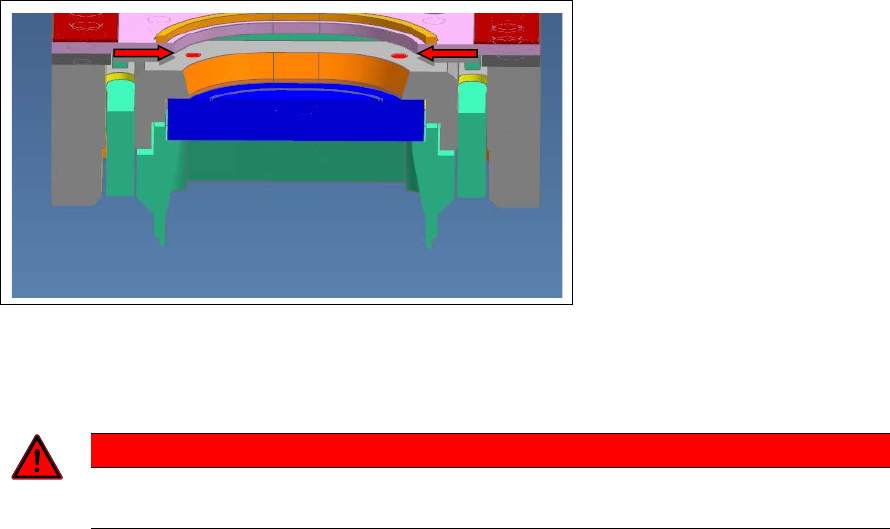
Within the field of view of the feeder camera there are two through-holes with a diameter of 1 mm
as fiducials for SIPLACE Vision in the Cartridge.
SIPLACE BulkFeeder X / Operating Manual 05/2017 Edition
14
Figure 3-3: Fiducials for SIPLACE Vision
The plate shutter can be opened and closed via the corresponding buttons on the feeder or under
Manual Operations on the station software GUI.
DANGER
Do not open the plate shutter manually! This may cause malfunction of the shutter ►
mechanism.
The container shutter is a shaft with a groove that runs in a sliding sleeve. The function of the
container shutter is to block the glass plate from being filled by slipping components when the
Cartridge is removed. For this, the components are vibrated behind the shutter and the shutter gets
closed before the Cartridge is removed.
The container shutter can be opened and closed via the corresponding buttons on the feeder or
under Manual Operations on the station software GUI.
3.3 Feeding principle
A vibration and shutter mechanism pours loose components onto a glass pickup plate. An
integrated camera takes a picture of the components from underneath the glass plate. The station
computer analyzes the image, identifies the components that are suitable for pickup and
determines their position and alignment.