00198045-01_OM_BulkFeeder_X_EN.pdf - 第20页
SIPLACE BulkFeede r X / Operating Ma nual 05/2017 Edition 20 4.3 Settings in the Station S oftware The SIPLACE B ulkFeeder X can be con figured togeth er with t he station softwar e . NOTICE Detailed infor mation on how …
SIPLACE BulkFeeder X / Operating Manual 05/2017 Edition
19
4.2 Settings in SIPLACE Pro
The SIPLACE BulkFeeder X can be configured together with SIPLACE Pro.
NOTICE
Detailed information on how to work with SIPLACE Pro can be found in the SIPLACE Pro
online help.
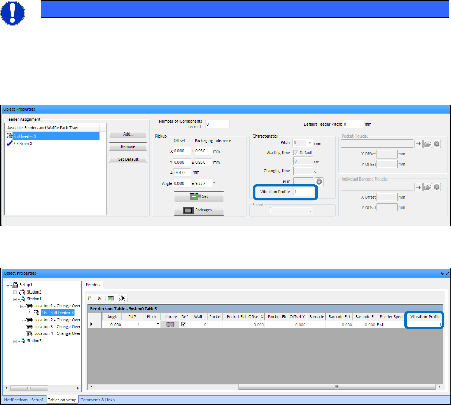
The Vibration Profile setting has to be set in the Component, Component Shape and Setup
Editors for the SIPLACE BulkFeeder X.
Figure 4-1: Component / Component Shape Editor – Vibration Profile setting
The vibration profile 1 is preset and is only supported.
Figure 4-2: Setup Editor – Vibration Profile setting
For Level 3 Optimization with feeder inventories, the SIPLACE BulkFeeder X is considered as an
alternative feeder type for 8 mm feeders.
The component face down recognition for resistors has to be enabled manually by the operator.
SIPLACE BulkFeeder X / Operating Manual 05/2017 Edition
20
4.3 Settings in the Station Software
The SIPLACE BulkFeeder X can be configured together with the station software.
NOTICE
Detailed information on how to work with the station software and the Vision software
can be found in the online help of the station software.
4.3.1 Setup
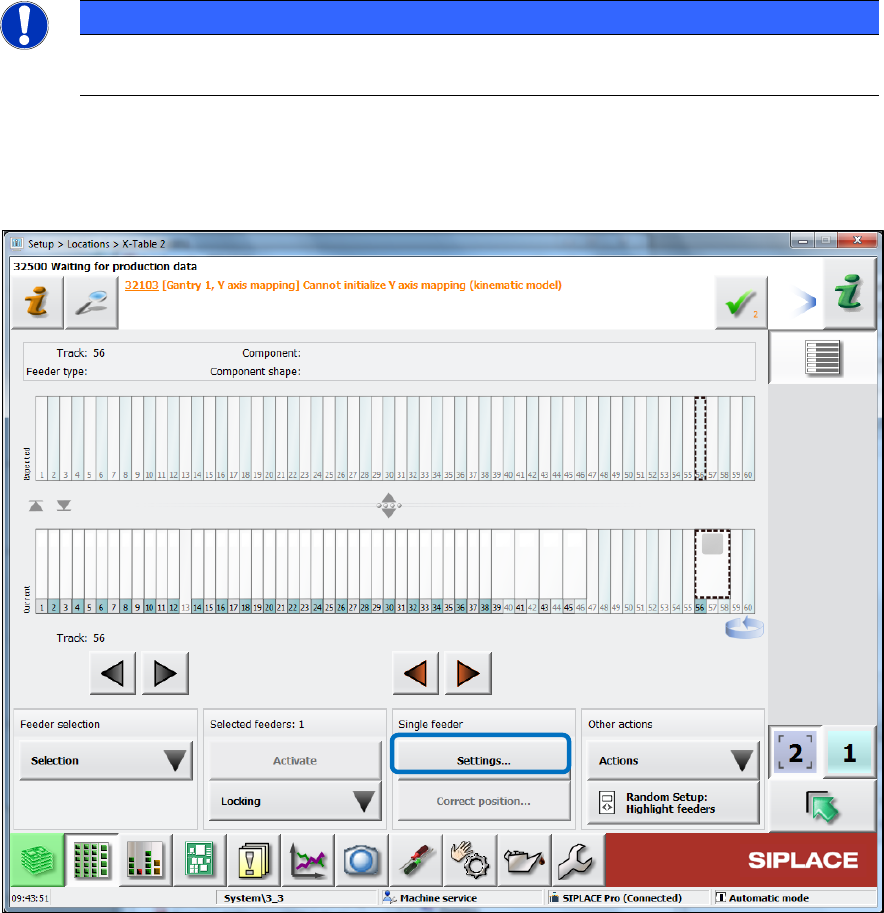
The feeder setup is displayed in the Table dialog for the location in the Setup view.
Figure 4-3: Feeder setup
Click on Settings… to display further data for the feeder. ►
SIPLACE BulkFeeder X / Operating Manual 05/2017 Edition
21
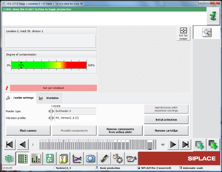
Figure 4-4: Feeder settings
In the Feeder settings tab, the feeder type and vibration profile are displayed. Additionally, you
can perform the following actions:
Select the Flash camera button to take a new image. ►
Select the Provide components button to vibrate the components onto the glass plate. ►
Select the Remove components from pickup plate button to vibrate the components back ►
from the pickup plate into the container.
Select the Remove cartridge button to remove the Cartridge from the Base Unit. ►
After changing the vibration profile, select the Synchronize with expected settings button to ►
restore the settings.
After removing the cartridge, select the Initial activation button. Calibration must be carried ►
out after a cartridge has been inserted in the base unit: This involves removing the components
from the pickup plate and measuring the camera position of the feeder again. Calibration is
performed automatically after a product has been specified or when a new board is moved in.