4OM-1064-001.pdf - 第136页
Tg0249-PM-MM *5 [TEACH ST ART] Key When this key is selected and the [MOVE] button is pressed, the P .E.C. recognition camera moves to the specified position of the selected vibra- tory stick feeder unit. The teaching po…
Tg0249-PM-MM
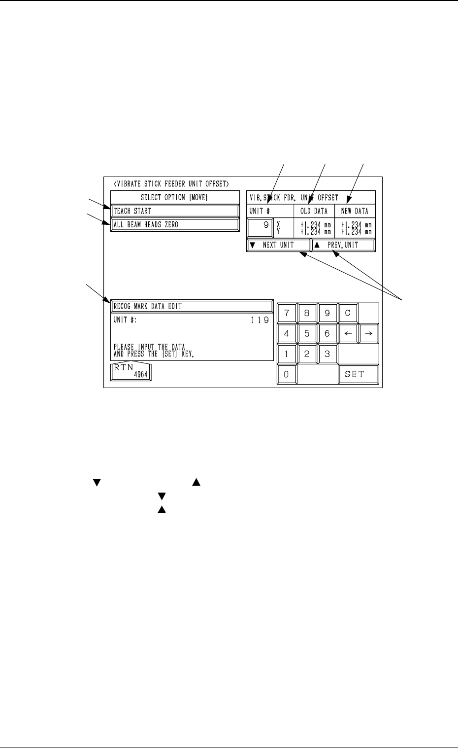
6.8.3 Vibratory Stick Feeder Unit Offset
• The offset data for the vibratory stick feeder unit can be taught through
manual alignment operation.
When the [VIBRATE STICK FDR. UNIT OFFSET] key is pressed at the “UNIT
MANUAL ALIGNMENT TEACH” display, the following display appears on
the screen.
*1 UNIT #
Set the vibratory stick feeder unit No. for manual alignment and teaching
operations.
*2 [
NEXT UNIT] and [ PREV. UNIT] Keys
Every time the [
NEXT UNIT] key is pressed, the unit No. increases by 1.
Every time the [
PREV. UNIT] key is pressed, the unit No. decreases by 1.
*3 [RECOG MARK DATA EDIT] Key
When this key is pressed, the “RECOG. MARK DATA EDIT” display (Fig.
3.63) appears on the screen, enabling the designation of a template shape to
appear on the recognition monitor.
The template shape can be specified for manual alignment with the align-
ment point.
Refer to “6.8.8 Editing of Recognition Mark Data” for details.
*4 [ALL BEAM HEADS ZERO] Key
Both Beams A and B are zeroed.
When this key is selected and the [MOVE] button is pressed, the zeroing
operation starts.
9910-001 3-89
6. TEACH OFFSET Display
Fig. 3.57
*1
*2
*5
*4
*3
*6
*7

Tg0249-PM-MM
*5 [TEACH START] Key
When this key is selected and the [MOVE] button is pressed, the P.E.C.
recognition camera moves to the specified position of the selected vibra-
tory stick feeder unit.
The teaching point of the vibratory stick feeder unit appears on the recogni-
tion monitor. Perform the manual alignment using the track ball.
Refer to “6.8.9 Teaching Operation with Trackball” for details.
*6 OLD DATA
Displayed are the values (the parameters related to the indicated unit #)
before the vibratory stick feeder unit offset data is taught.
*7 NEW DATA
Displayed are the values (the parameters related to the indicated unit #)
after the vibratory stick feeder unit offset data is taught.
Before the teaching operation is performed, the same values as *6 are dis-
played.
9910-001 3-90
6. TEACH OFFSET Display
Tg0249-PM-MM
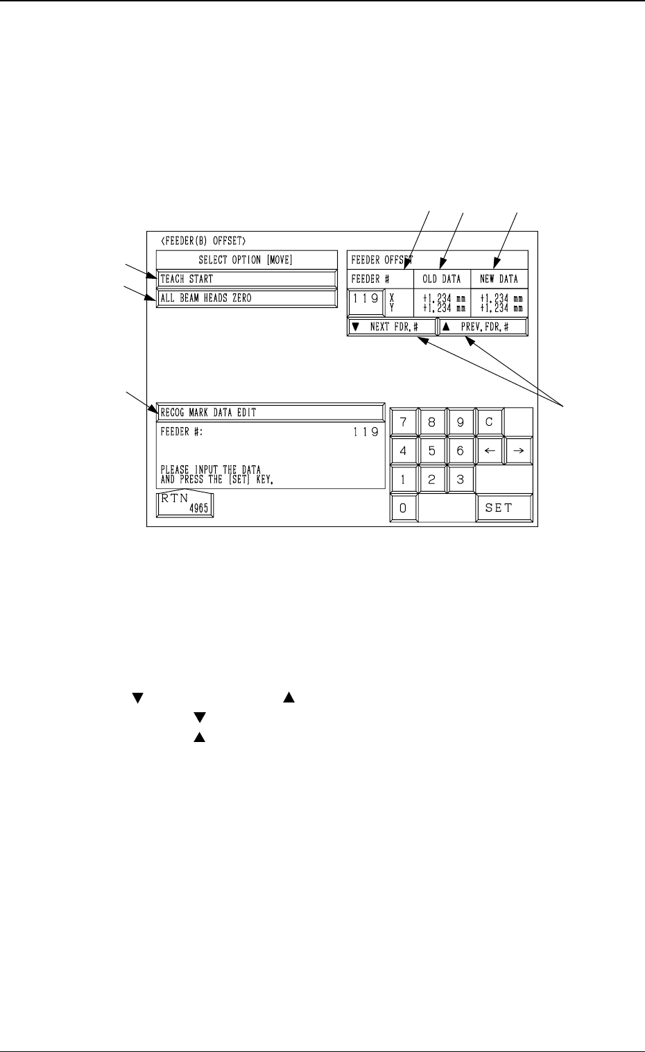
6.8.4 Feeder (B) Offset
• After the actually used feeders are installed in each feeder slot No. and
manual alignment operation is performed, the offset values for the feeder
are taught.
When the [FEEDER (B) OFFSET] key is pressed at the “UNIT MANUAL
ALIGNMENT TEACH” display, the following display appears on the screen.
*1 FEEDER #
A feeder slot No. can be set for manual alignment and teaching operations.
Install the feeder to be used in the slot No. specified in the “FEEDER #”
data box.
*2 [
NEXT FDR. #] and [ PREV. FDR. #] Keys
When the [
NEXT FDR. #] key is pressed, the feeder # increases by 1.
When the [
PREV. FDR. #] key is pressed, the feeder # decreases by 1.
*3 [RECOG MARK DATA EDIT] Key
When this key is pressed, the “RECOG. MARK DATA EDIT” display (Fig.
3.63) appears on the screen, enabling the designation of a template shape to
appear on the recognition monitor.
The template shape can be specified for manual alignment with the align-
ment point.
Refer to “6.8.8 Editing of Recognition Mark Data” for details.
*4 [ALL BEAM HEADS ZERO] Key
Both Beams A and B are zeroed.
When this key is selected and the [MOVE] button is pressed, the zeroing
operation starts.
*1
*2
*5
*4
*3
*6
*7
9910-001 3-91
6. TEACH OFFSET Display
Fig. 3.58