4OM-1064-001.pdf - 第168页
Tg0249-PM-MM *2 “SELECT OPTION” [FEEDER (B) OFFSET] Key When the display (Fig. 3.80-2) is active and this key is pressed, the display (Fig. 3.80-1) appears on the screen. Use this function to perform the teaching operati…
Tg0249-PM-MM
6.12.2 FEEDER (B) OFFSET
••
••
•
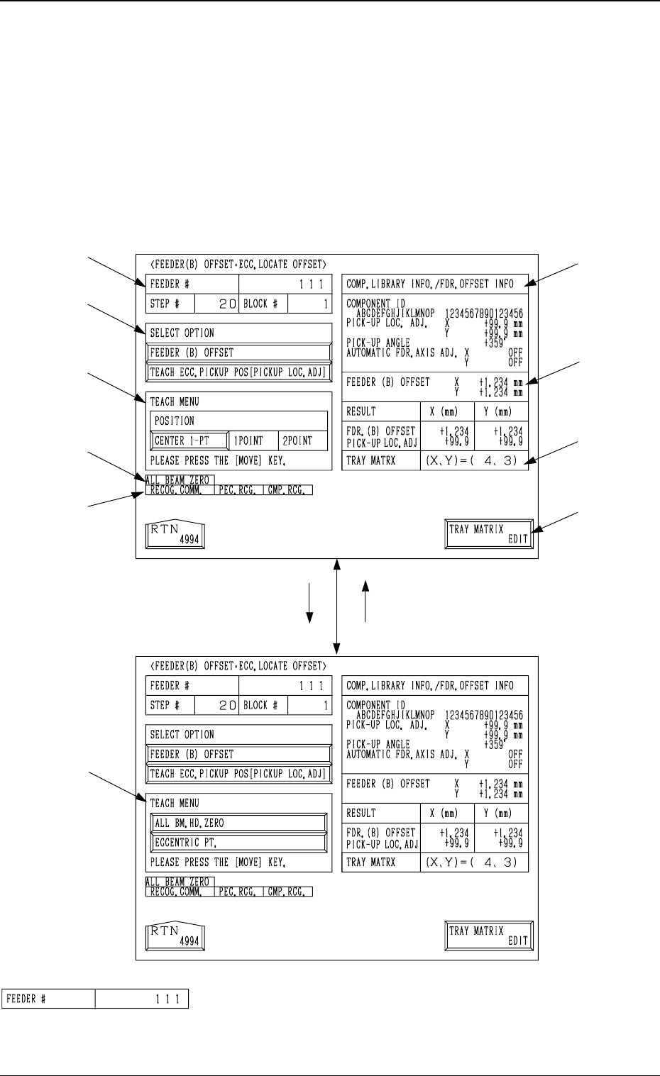
ECC. LOCATE OFFSET
Display (Option)
• This display allows the teaching operation on the feeder (B) offset and ec-
centric pick-up location of the multi-layer tray feeder (option).
When the [FEEDER (B) OFFSET ECC. LOCATE POSITION] key is pressed
at the “PICK-UP LOCATION (TRAY)” display, the following display appears
on the screen.
*1 “FEEDER #”
Shown is the feeder No. which was specified at the display
(Fig. 3.76).
[TEACH ECC. PICKUP POS
[PICKUP LOC. ADJ]] Key
[FEEDER (B) OFFSET] Key
*1
*2
*3
*9
*10
*4
*5
*6
*7
*8
9910-001 3-121
6. TEACH OFFSET Display
Fig. 3.80-1
Fig. 3.80-2
Tg0249-PM-MM
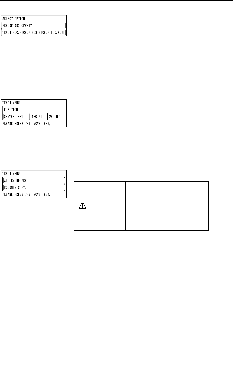
*2 “SELECT OPTION”
[FEEDER (B) OFFSET] Key
When the display (Fig. 3.80-2) is active and this key is
pressed, the display (Fig. 3.80-1) appears on the screen.
Use this function to perform the teaching operation on
the component center position.
[TEACH ECC. PICKUP POS [PICKUP LOC. ADJ]] Key
When the display (Fig. 3.80-1) is active and this key is
pressed, the display (Fig. 3.80-2) appears on the screen.
Use this function when a component has a groove, a
protrusion, etc., and cannot be picked up at the center
without any hindrance.
*3 “TEACH MENU”
“FEEDER (B) OFFSET (X, Y)” is modified additionally.
[CENTER 1-PT.] Key
When this key is pressed, the X/Y beam moves to the
center of the component.
“1POINT” and “2POINT”
These labels are used to align the component with two
diagonally-located points.
When the maximum outside dimensions of the compo-
nent exceeds “10 × 10 mm”, use these keys.
*4 “TEACH MENU”
CAUTION
“PICK-UP LOCATION AD-
JUSTMENT X, Y” in the com-
ponent library data is modified
additionally.
Incorrect teaching operation will
cause the pick-up rate to dete-
riorate.
[ALL BM. HD. ZERO] Key
This key is used to zero both Beams A and B.
When this key is selected and the [MOVE] button is
pressed, the zeroing operation starts.
[ECCENTRIC PT.] Key
When this key is selected and the [MOVE] button is
pressed, the P.E.C. recognition camera moves to the des-
ignated pick-up location correction position based on
the component center position (Position of “Design Po-
sition + Feeder (A) Offset + Feeder (B) Offset”) of the
pertinent feeder, making it possible to capture the im-
age.
Under this condition, shift to the trackball operation and
perform the manual alignment operation.
Note: It is necessary to correctly teach the component
center position before the eccentric position is
adjusted.
9910-001 3-122
6. TEACH OFFSET Display
Tg0249-PM-MM
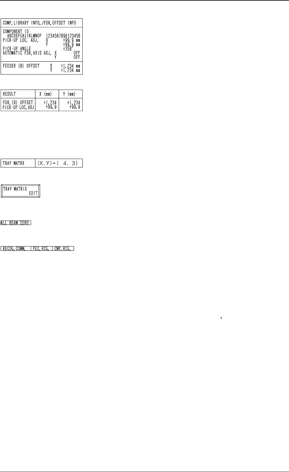
*5 “COMP. LIBRARY INFO./FDR. OFFSET INFO”
Displayed are the component library data and the feeder
offset of the feeder No. set up in *1.
*6 “RESULT X (mm), Y (mm)”
When the manual alignment operation (using the trackball)
is completed, the results of the teaching operation are dis-
played.
Selection of [FEEDER (B) OFFSET] Key: FEEDER (B)
OFFSET
Selection of [TEACH ECC. PICKUP POS [PICKUP LOC.
ADJ]] Key: PICK-UP LOCATION ADJUSTMENT
*7 “TRAY MATRIX”
Shown are the coordinates (X, Y) which represent the pick-
up matrices of the selected tray.
*8 [TRAY MATRIX EDIT] Key
When this key is pressed, the display (Fig. 3.81) appears
on the screen.
Use this function to edit the pick-up matrices.
*9 “ALL BEAM ZERO”
When all beams are zeroed completely, the background turns
green. Otherwise, the background has no color.
*10 “RECOG. COMM.”
When “DISABLE” is set in the “P.E.C.” and “COMPO
NENT RECOGNITION” data boxes at the “TEST
MODE” display, the background color of “P.E.C. RECOG.”
and “COMP. RECOG.” becomes light red.
(No background color in normal cases)
Operation Procedure
Refer to “6.10 PICK-UP LOCATION (TAPE
VIB. STICK)
Display” for details.
9910-001 3-123
6. TEACH OFFSET Display