4OM-1064-001.pdf - 第231页
9910-001 Tg0249-PM-MM 8. DEVICE CHECK Display 3-185 3-185 T able 3.14 Stick Feeder Setting of SDS Nodes for Feeder Base R (A) (Option) T able 3.15 Stick Feeder Setting of SDS Nodes for Feeder Base L (A) (Option) T able 3…
9910-001 Tg0249-PM-MM
3-184
8. DEVICE CHECK Display8. DEVICE CHECK Display
Table 3.13
Setting of Tray R SDS Nodes (Option)
Table 3.12
Setting of Tray L SDS Nodes (Option)
0103-002 3-184 Tg0249-PM-MM
9910-001 Tg0249-PM-MM
8. DEVICE CHECK Display
3-1853-185
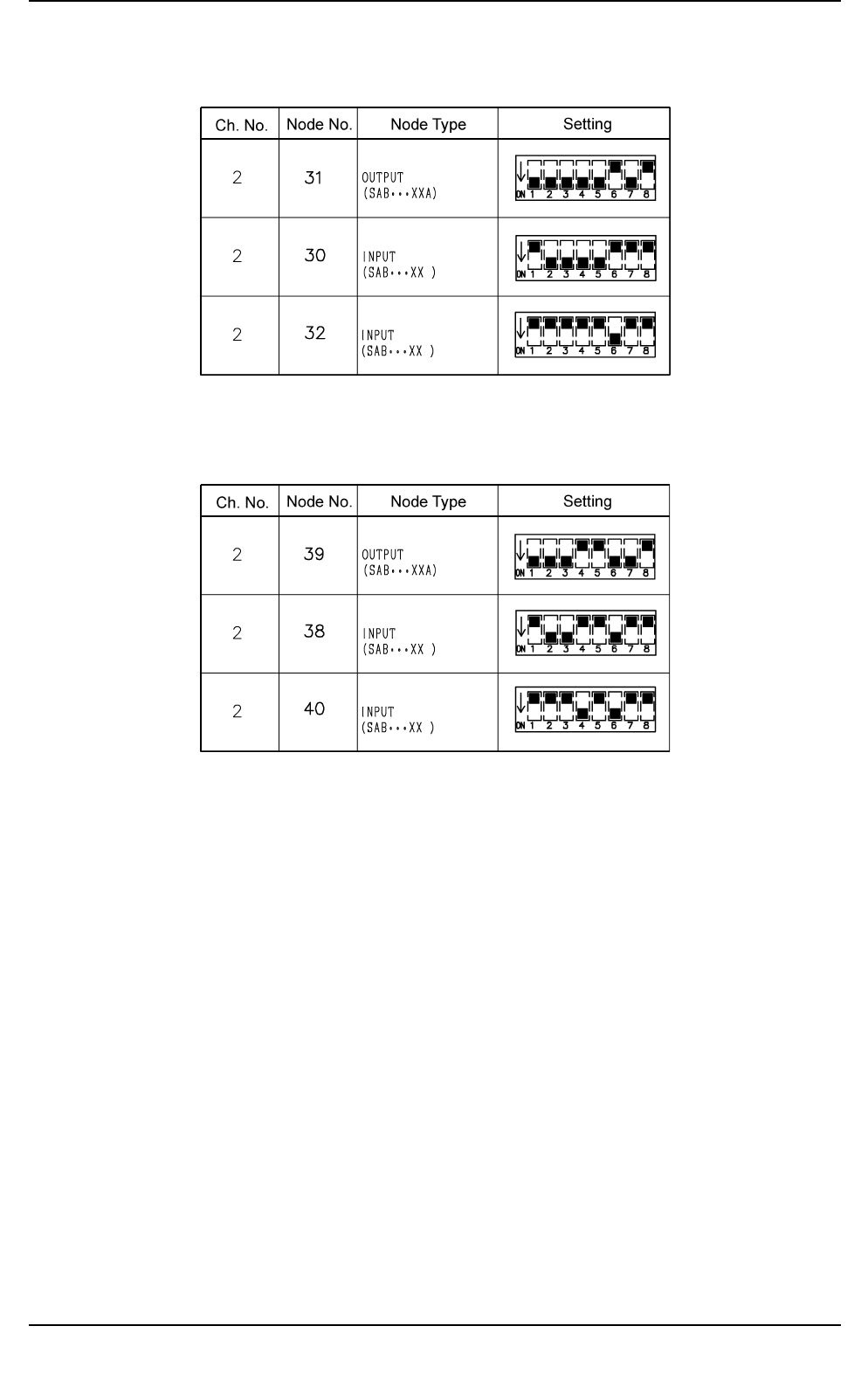
Table 3.14
Stick Feeder Setting of SDS Nodes for Feeder Base R (A) (Option)
Table 3.15
Stick Feeder Setting of SDS Nodes for Feeder Base L (A) (Option)
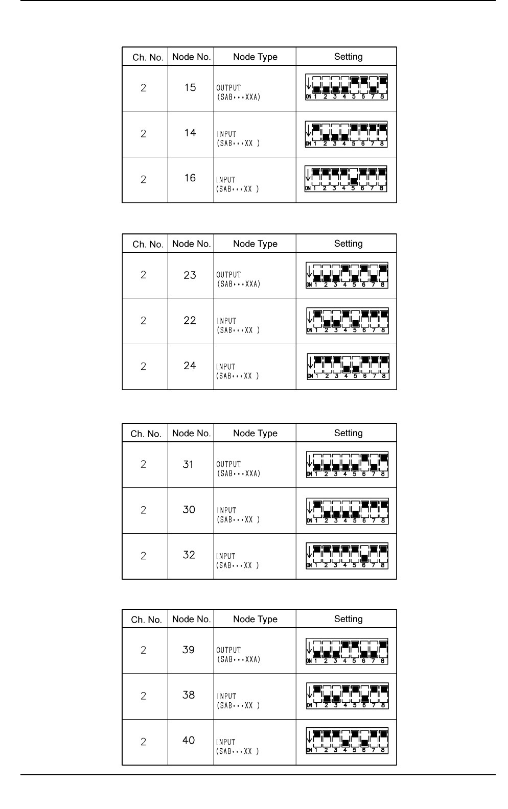
Table 3.16
Stick Feeder Setting of SDS Nodes for Feeder Base R (B) (Option)
0103-002 Tg0249-PM-MM
Table 3.17
Stick Feeder Setting of SDS Nodes for Feeder Base L (B) (Option)
9910-001 Tg0249-PM-MM
8. DEVICE CHECK Display
3-186
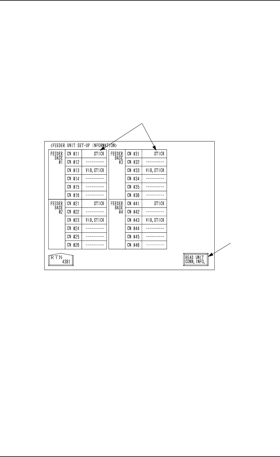
8.1.5 FEEDER UNIT SET-UP INFORMATION Display
• Displayed are the names of the feeders installed on the feeder base units #1
through #4.
When the [FEEDER UNIT SET-UP INFO.] key is pressed at the “INPUT
CHECK” display, the following display (Fig. 3.107) appears on the screen.
Note: When the connection of the unit is changed after this display is opened,
be sure to press the [READ UNIT CONN. INFO.] key. Otherwise, the
correct device information will not be displayed.
*1 Indicated are what types of feeders are connected with which connectors.
*2 [READ UNIT CONN. INFO.] Key
This key is used to update the feeder unit set-up information.
*2
*1
Fig. 3.107