4OM-1064-001.pdf - 第93页
Tg0249-PM-MM *5 *6 *8 *10 *7 *9 *1 1 *4 *3 *3 *2 *1 9910-001 3-47 6. TEACH OFFSET Display Fig. 3.30 6.1 P .E.C. RECOG CAMERA & BEAM OFFSET (STEP-1) Display • This display allows teaching the offset data for Beams A a…
Tg0249-PM-MM
Notes: (a) When “P.E.C. Recognition Camera & Beam Offset (Step 1)” must
be taken, perform the teaching operation of [Teaching Plate Off-
set] before [Component Recognition Camera Offset (Step 3)].
In this case, also perform the following teaching operation after
teaching of “Head Offset (Get Both Image)” is complete.
“Nozzle Stoker Offset”
“Traverse Offset (Option)”
(b) After the head section is changed, perform the teaching operation
on the lighting at the “LIGHTING” display before “Component
Recognition Camera Magnification (Step 2)”. (Hierarchical Se-
quence: “SPECIAL SEL.” Display → “UNIT ADJUSTMENT”
Display → “LIGHTING” Display)
0004-002 3-46
6. TEACH OFFSET Display
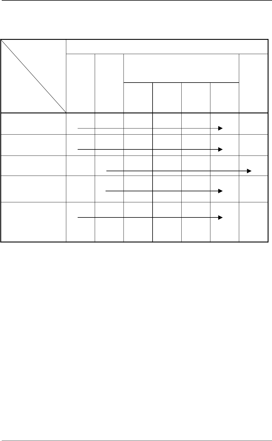
Order of Teaching Operations: The {-marked items should be implemented
sequentially from the left to the right one.
Camera head offset teaching available
Teaching Items
Operational Items
P. E . C .
Recognition
Camera &
Beam Offset
(Step 1)
Component
Recognition
Camera
Magnification
(Step 2)
Component
Recognition
Camera
Offset
(Step 3)
Head
Center
Offset
Head
Offset
Head
Offset
(Get Both
Image)
Head
Rotation
Offset
P.C.B. Recognition
Camera Change
{
*1
{
*2
{
*3
{
*4
{
*5
Motor for Readjustment of
Beam Origin, Slide Origin
Sensor Change, Others
{
*1
{
*2
{
*3
{
*4
{
*5
Change of Head Section
Note: (b)
{
*1
{
*2
{
*3
{
*4
{
*5
{
*6
Component Recognition
Camera Change
(View Change, etc.)
{
*1
{
*2
{
*3
{
*4
{
*5
Maintenance of P.C.B.
Positioning Section
x Stopper Change
xTransfer Section including
Fixed Chute
Unit Change
{
*1
{
*2
{
*3
{
*4
{
*5
Table 3.3 List of Operational and Teaching Items
(items which require the offset teaching)
Tg0249-PM-MM
*5
*6
*8
*10
*7*9
*11
*4
*3
*3
*2
*1
9910-001 3-47
6. TEACH OFFSET Display
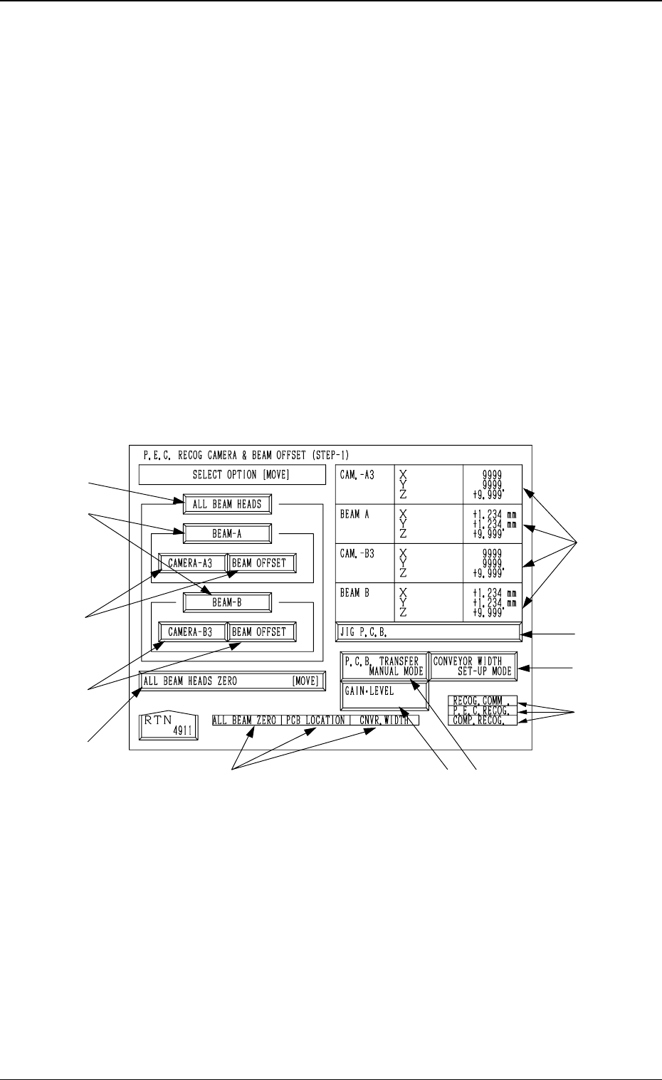
Fig. 3.30
6.1 P.E.C. RECOG CAMERA & BEAM OFFSET
(STEP-1) Display
• This display allows teaching the offset data for Beams A and B and the
offset data for the P.E.C. recognition camera.
The patterns printed on the positioned special jig P.C.B. (option) are recog-
nized by the P.E.C. recognition camera and each offset data is calculated
through the recognition.
Notes: (a) A special jig P.C.B. (option) is required.
The parameters are factory-set at shipment. It is not necessary to
teach these parameters.
(b) Follow the teaching procedures in the specified order. Otherwise,
some trouble (such as inaccurate component placement, frequent
mechanical errors, etc.) will arise.
When the [P.E.C. RECOG CAMERA & BEAM OFFSET (STEP-1)] key is
pressed at the “TEACH OFFSET” display, the following display appears on
the screen.
Tg0249-PM-MM
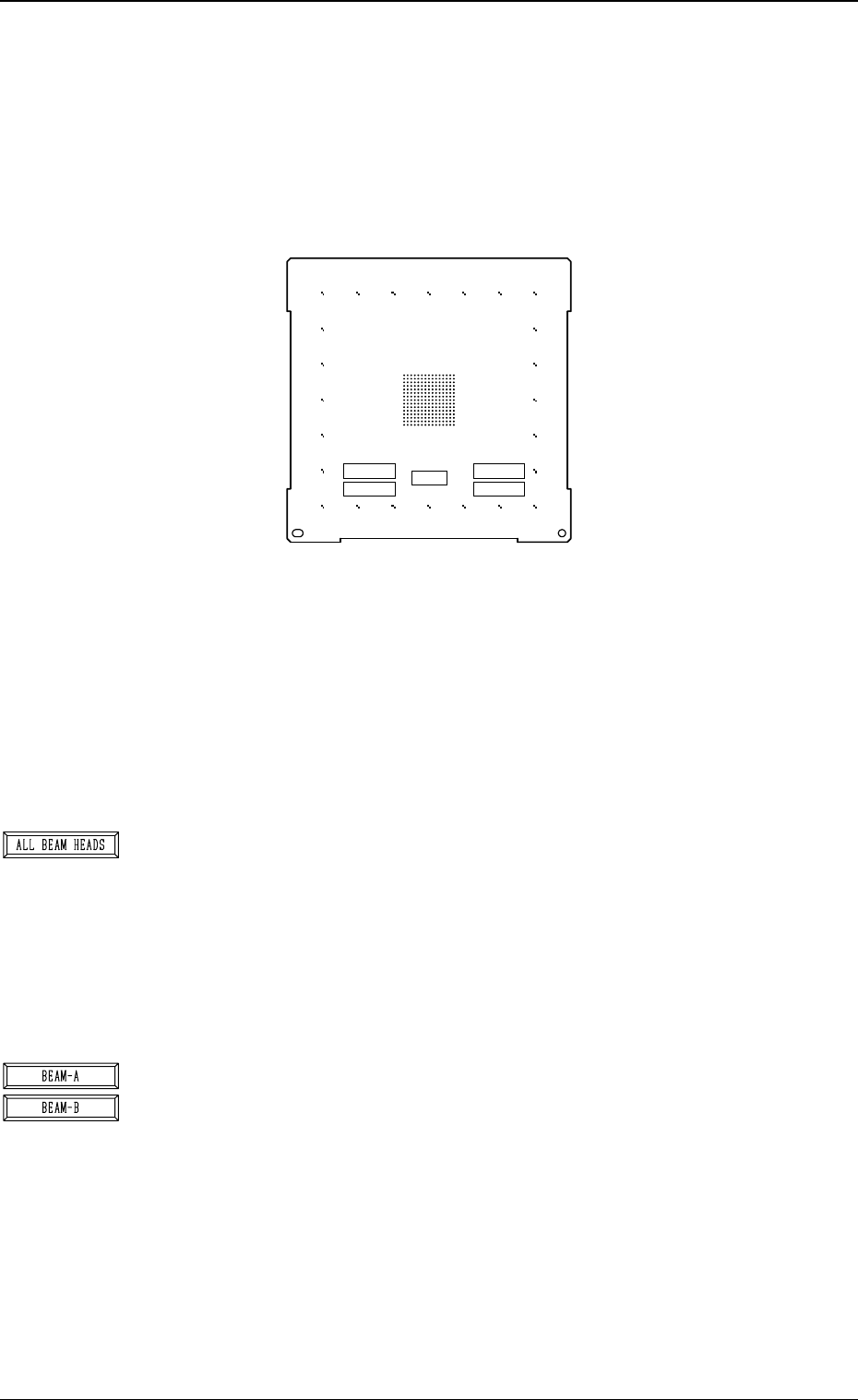
Special Jig P.C.B. (Option)
Note: Consult our sales personnel for the detailed information on how to use
the special jig P.C.B.
Name : P.C.B. Recognition Calibration Jig
Model Name : JG-0086
Dimensions : Approx. 160 (width) × 160 (depth) × 1.6 (thickness) mm
• The special jig P.C.B. has printed round marks forming a matrix on its
center. The marks are used to calculate the magnification and angle of
the selected camera.
Checker marks are also printed around the matrix and used to calculate
the angle between the P.E.C. recognition camera magnification beam X/
Y axis and the P.C.B. positioning X/Y coordinates (orthogonal degree
of vertical and horizontal axis).
*1 [ALL BEAM HEADS] Key
The machine performs the teaching operation of the P.E.C. recognition
camera and beam offset data related to both Beams A and B.
When this key is selected and the [MOVE] button is pressed, the ma-
chine starts the teaching operation.
The teaching operation is performed first on Beam A and then on Beam
B.
Note: Before performing any teaching operation, position the jig P.C.B.
and zero both beams.
*2 [BEAM-A] and [BEAM-B] Keys
The machine performs the teaching operation of the P.E.C. recognition
camera and beam offset data related to either Beam A or Beam B.
When the [BEAM-A] or the [BEAM-B] key is selected and the [MOVE]
button is pressed, the machine starts the teaching operation related to
the selected beam.
The machine performs the teaching operation related to either Beam A
or Beam B.
Note: Before performing any teaching operation, position the jig P.C.B.
and zero both beams.
0004-002 3-48
6. TEACH OFFSET Display
Fig. 3.31
X=
Y=
X=
Y=
NOTICE
DON'T TOUCH THE PRINTED PATTERN
MARK1
MARK2
JIG ROTATION
(MARK1-MARK2)
MARK1 MARK2