4OM-1064-001.pdf - 第95页
Tg0249-PM-MM *3 [CAMERA-A3] and [BEAM OFFSET] Keys in “BEAM- A” Group Box and [CAMERA-B3] and [BEAM OFFSET] Keys in “BEAM-B” Group Box The machine performs the offset teaching operation for each individual units (devices…
Tg0249-PM-MM
Special Jig P.C.B. (Option)
Note: Consult our sales personnel for the detailed information on how to use
the special jig P.C.B.
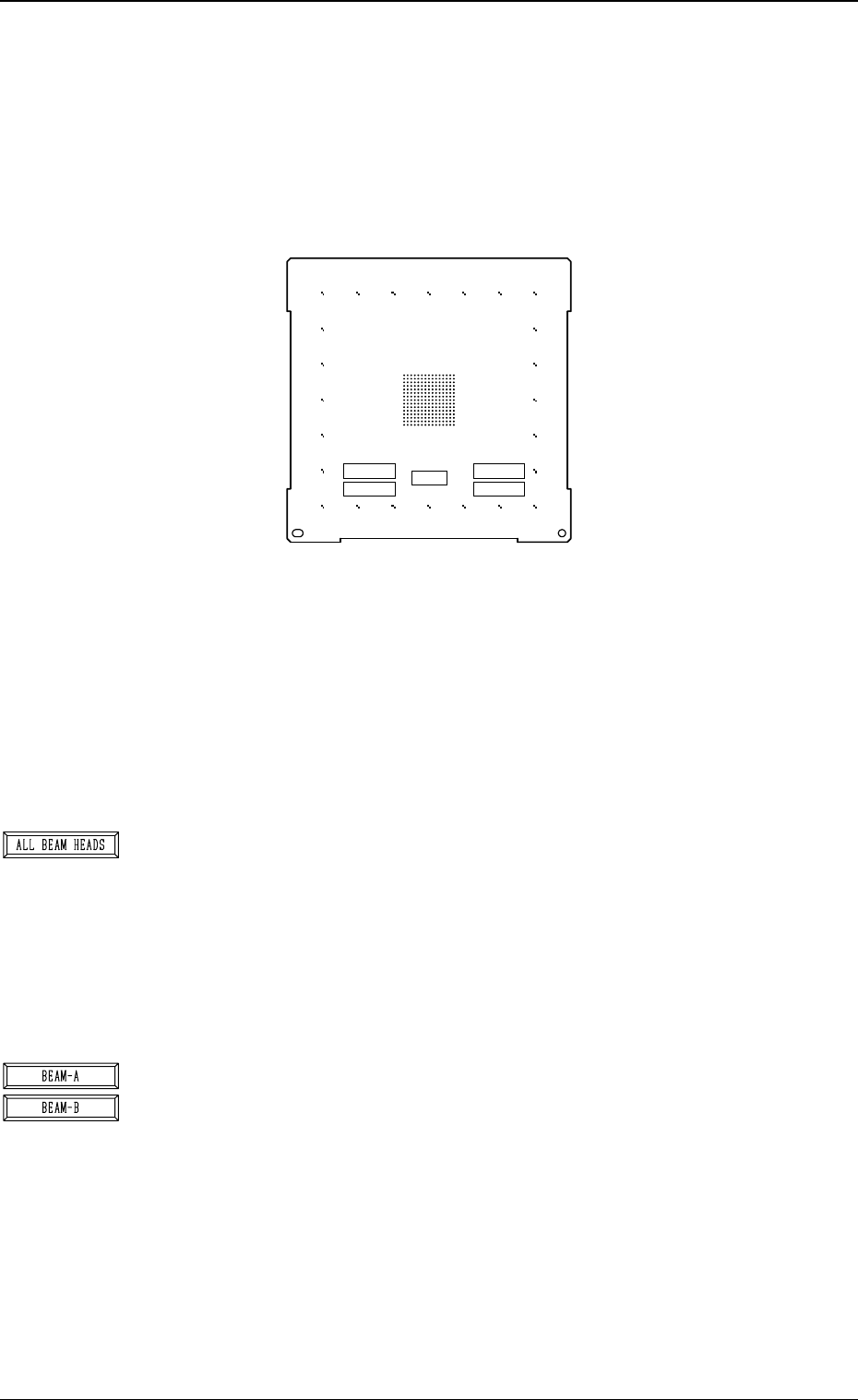
Name : P.C.B. Recognition Calibration Jig
Model Name : JG-0086
Dimensions : Approx. 160 (width) × 160 (depth) × 1.6 (thickness) mm
• The special jig P.C.B. has printed round marks forming a matrix on its
center. The marks are used to calculate the magnification and angle of
the selected camera.
Checker marks are also printed around the matrix and used to calculate
the angle between the P.E.C. recognition camera magnification beam X/
Y axis and the P.C.B. positioning X/Y coordinates (orthogonal degree
of vertical and horizontal axis).
*1 [ALL BEAM HEADS] Key
The machine performs the teaching operation of the P.E.C. recognition
camera and beam offset data related to both Beams A and B.
When this key is selected and the [MOVE] button is pressed, the ma-
chine starts the teaching operation.
The teaching operation is performed first on Beam A and then on Beam
B.
Note: Before performing any teaching operation, position the jig P.C.B.
and zero both beams.
*2 [BEAM-A] and [BEAM-B] Keys
The machine performs the teaching operation of the P.E.C. recognition
camera and beam offset data related to either Beam A or Beam B.
When the [BEAM-A] or the [BEAM-B] key is selected and the [MOVE]
button is pressed, the machine starts the teaching operation related to
the selected beam.
The machine performs the teaching operation related to either Beam A
or Beam B.
Note: Before performing any teaching operation, position the jig P.C.B.
and zero both beams.
0004-002 3-48
6. TEACH OFFSET Display
Fig. 3.31
X=
Y=
X=
Y=
NOTICE
DON'T TOUCH THE PRINTED PATTERN
MARK1
MARK2
JIG ROTATION
(MARK1-MARK2)
MARK1 MARK2
Tg0249-PM-MM
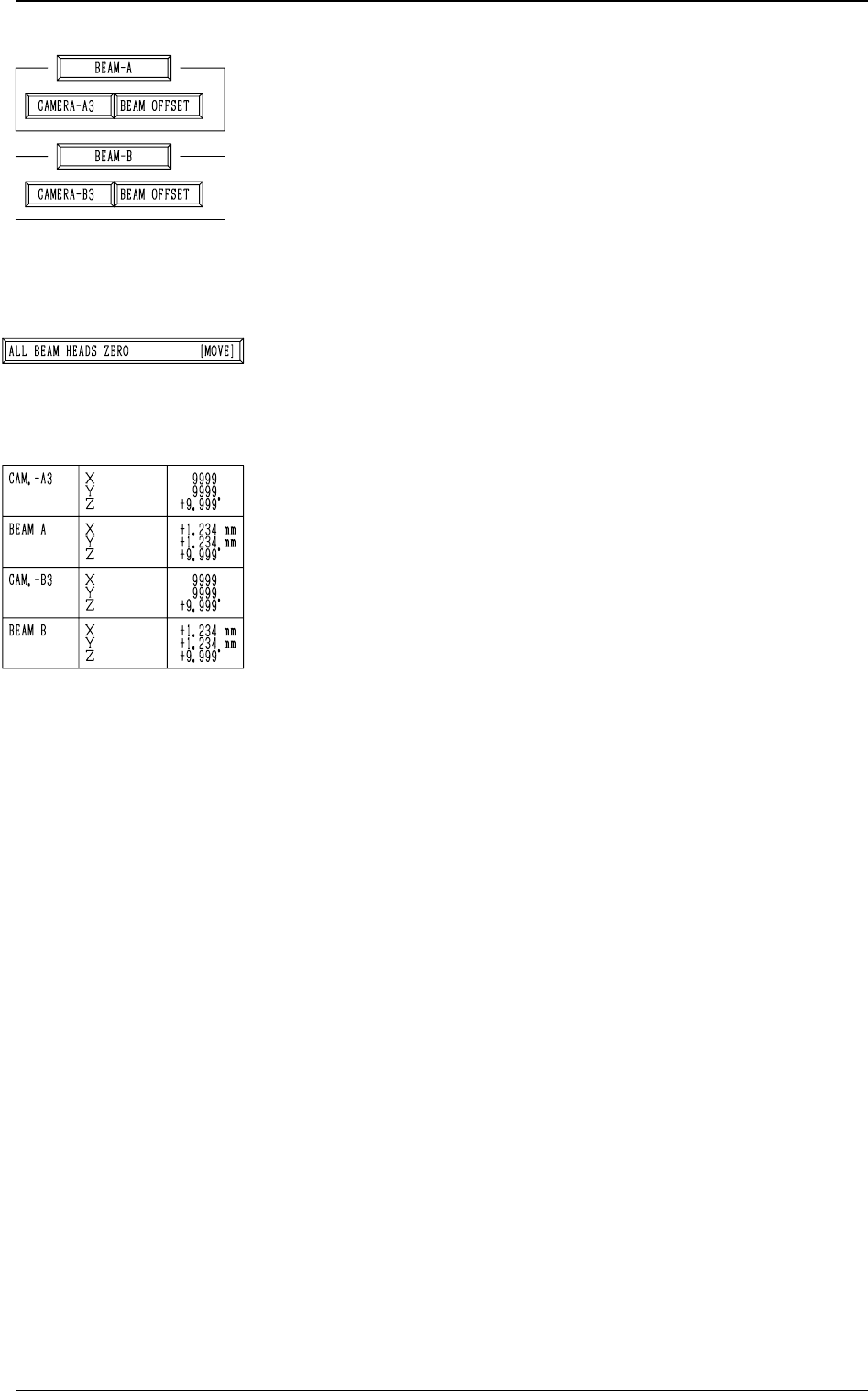
*3 [CAMERA-A3] and [BEAM OFFSET] Keys in “BEAM-
A” Group Box and [CAMERA-B3] and [BEAM OFFSET]
Keys in “BEAM-B” Group Box
The machine performs the offset teaching operation for each
individual units (devices).
When one of the above-described keys is selected and the
[MOVE] button is pressed, the machine starts teaching the
offset data related to the selected unit (device).
Note: Before performing any teaching operation, position
the jig P.C.B. and zero both beams.
*4 [ALL BEAM HEADS ZERO [MOVE]] Key
Both Beams A and B are zeroed.
When this key is selected and the [MOVE] button is pressed,
the zeroing operation starts.
*5 The following offset values are shown.
• Offset Values for Beam A:
“X (Horizontal)”, “Y (Vertical)”, and “Z (Theta)”
• Offset Values for Beam B:
“X (Horizontal)”, “Y (Vertical)”, and “Z (Theta)”
• Offset Values for Camera-A3 (P.E.C. Camera A3):
“Z (Theta)”
• Offset Values for Magnification of Camara-A3:
“X (Horizontal)” and “Y (Vertical)”
• Offset Values for Camera-B3 (P.E.C. Camera B3):
“Z (Theta)”
• Offset Values for Magnification of Camera-B3:
“X (Horizontal)” and “Y (Vertical)”
9910-001 3-49
6. TEACH OFFSET Display
Tg0249-PM-MM
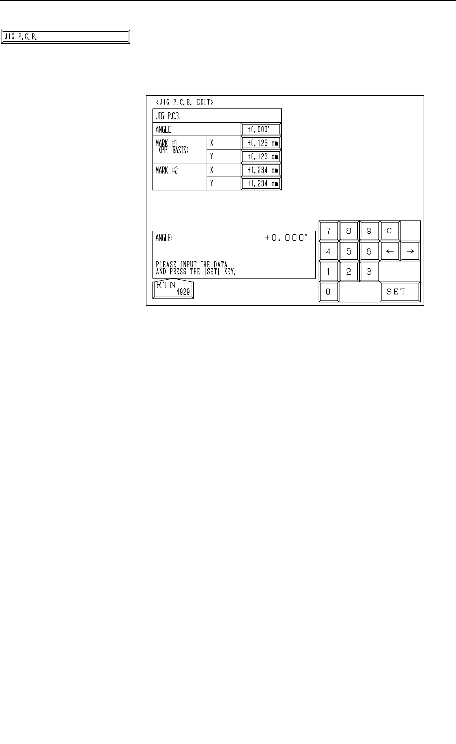
*6 [JIG P.C.B.] Key
When this key is pressed, the “JIG P.C.B. EDIT” display
(Fig. 3.32) appears on the screen, enabling the entry of pa-
rameters related to the jig P.C.B.
• A parameter can be entered in each data box.
The parameters (X and Y) for “MARK #1 (PP. BASIS)”
are the coordinates (distances) based on the reference
point for P.C.B. positioning.
Enter the numeric values described on the jig P.C.B.
9910-001 3-50
6. TEACH OFFSET Display
Fig. 3.32