4OM-1064-001.pdf - 第78页
9910-001 Tg0249-PM-MM 3.3.5 Nozzle Management Data When the [NOZZLE MANAGEMENT DA T A] key is pressed at the “MAN- AGEMENT DA T A (TYPE 1)” display , the following display appears on the screen. Pressing the [SCREENS] ke…
9910-001 Tg0249-PM-MM
[HEAD CLEAR/CHANGE DATE] Key
Shown are the updated dates for each head. (based on head bypassing, etc.)
[COMM. ERROR] Key
Shown is the number of communication errors for each head.
[ORIGIN ERROR] Key
Shown is the number of head origin errors for each head.
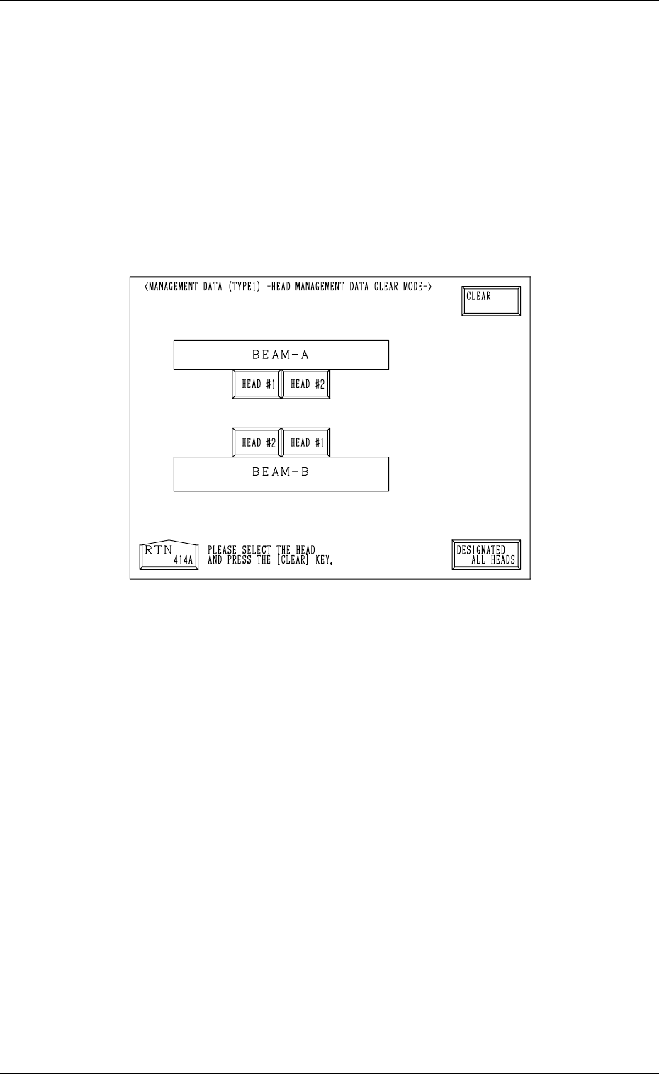
How to Clear the Head Management Data
(1) Press the [CLEAR HEAD MGT. DATA] key.
The following display appears on the screen.
(2) Select one of the head # keys whose management data should be cleared.
• To select the head Nos. individually, press the related head # key.
The selected head # key turns blue.
• To select all head # keys at a time, press the [DESIGNATED ALL
HEADS] key.
All head # keys turn blue, indicating that all heads are designated.
(3) Press the [CLEAR] key.
The management data of the selected head No. is cleared.
(The date when the [CLEAR] key is pressed is displayed in the “HEAD
CLEAR/CHANGE DATE” text field.)
3-31
3. MANAGEMENT DATA Display
Fig. 3.18
9910-001 Tg0249-PM-MM
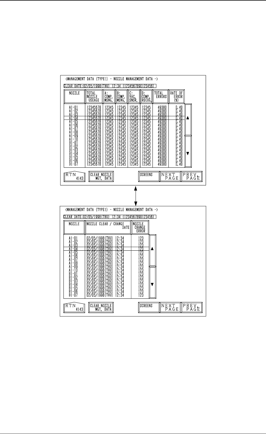
3.3.5 Nozzle Management Data
When the [NOZZLE MANAGEMENT DATA] key is pressed at the “MAN-
AGEMENT DATA (TYPE 1)” display, the following display appears on the
screen.
Pressing the [SCREENS] key at this display opens another “MANAGEMENT
DATA (TYPE1) - NOZZLE MANAGEMENT DATA -” display.
Note: When one of the data keys is pressed, the feeder No. with the biggest
parameter under the selected data key is displayed in the first line and
feeder Nos. having the subsequent (second, third, fourth, ...) biggest
parameters follow.
When the [NOZZLE] key is pressed, nozzle Nos. are arranged in their
initial order.
[NOZZLE] Key
Shown are the nozzle stocker and nozzle Nos.
[TOTAL NOZZLE USAGE] Key
Shown is the number of pick-up operations for each nozzle.
[A: COMP. MSNG.] Key
Shown is the number of missing components detected by the vacuum sen-
sor for each nozzle.
Fig. 3.19-1
Fig. 3.19-2
3-32
3. MANAGEMENT DATA Display
[SCREENS] Key
9910-001 Tg0249-PM-MM
[B: COMP. MSNG.] Key
Shown is the number of missing components detected in the recognition
processing for each nozzle.
[C: VAC. SNSR]
Key
Shown is the total number of component pick-up errors detected by the
vacuum sensor (errors not detected through the component recognition) for
each individual feeders.
[D: COMP. RECOG.] Key
Shown is the number of errors detected by the recognition processing for
each nozzle.
[TOTAL ERRORS] Key
Shown is the total number of errors detected by the above-described func-
tions ([A: COMP. MSNG.] through [D: COMP. RECOG.] keys).
[RATE OF ERROR (%)] Key
Shown are the percentages of errors per number of components to be picked
up.
[NOZZLE CLEAR/CHANGE DATE] Key
Shown are the updated dates for each nozzle.
[NOZZLE CHANGE ERROR] Key
Shown is the total number of errors detected during nozzle change opera-
tion.
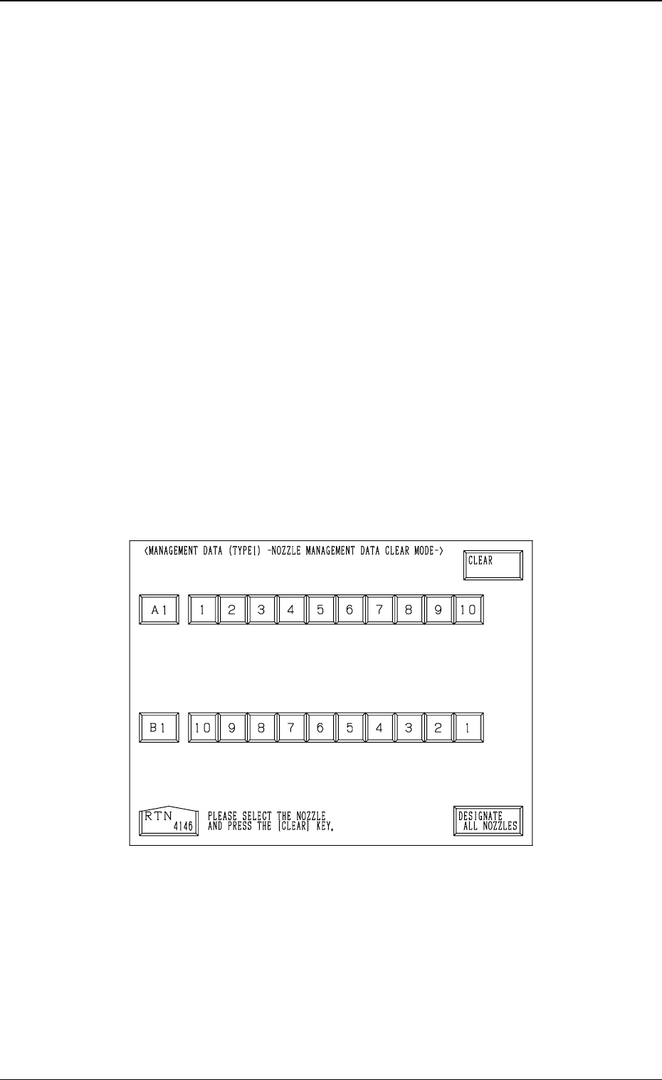
How to Clear the Nozzle Management Data
(1) Press the [CLEAR NOZZLE MGT. DATA] key.
The following display appears on the screen.
(2) Select one of the nozzle # keys whose management data should be cleared.
• To select the nozzle Nos. individually, press the related nozzle # key.
The selected nozzle # key turns blue.
• To select all nozzle # keys at a time, press the [DESIGNATE ALL
NOZZLES] key.
All nozzle # keys turn blue, indicating that all nozzles are designated.
(3) Press the [CLEAR] key.
The management data of the selected nozzle # is cleared.
(The date when the [CLEAR] key is pressed is displayed in the “NOZZLE
CLEAR/CHANGE DATE” text field.)
3-33
3. MANAGEMENT DATA Display
Fig. 3.20