4OM-1064-001.pdf - 第227页
9910-001 Tg0249-PM-MM 8. DEVICE CHECK Display 3-181 8.1.4 Setting of SDS Nodes Notes: (a) If the dip switches are not set correctly , normal performance will not be expected. (b) Note that the dip switches may be oriente…
9910-001 Tg0249-PM-MM
8. DEVICE CHECK Display
3-180
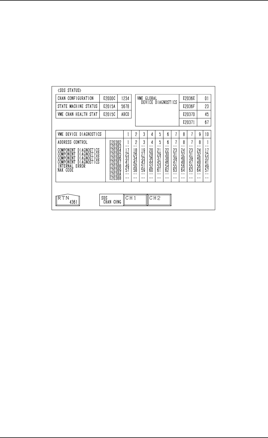
8.1.3 SDS STATUS Display
• Shown is the state of each channel.
This display is prepared only for a service personnel.
When the [SDS STATUS] key is pressed at the “INPUT CHECK” display, the
following display appears on the screen.
Fig. 3.106
9910-001 Tg0249-PM-MM
8. DEVICE CHECK Display
3-181
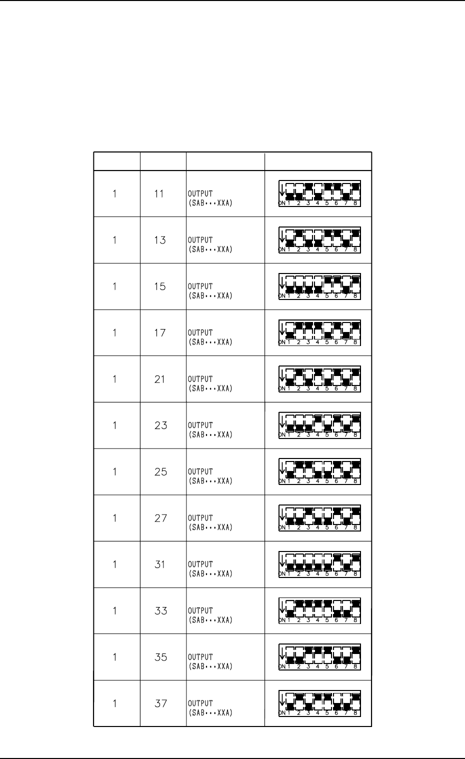
8.1.4 Setting of SDS Nodes
Notes: (a) If the dip switches are not set correctly, normal performance will
not be expected.
(b) Note that the dip switches may be oriented differently.
Setting of SDS Output Nodes (Main Body)
Table 3.5
Ch. No.
Node No.
Node Type
Setting
9910-001 Tg0249-PM-MM
8. DEVICE CHECK Display
3-182
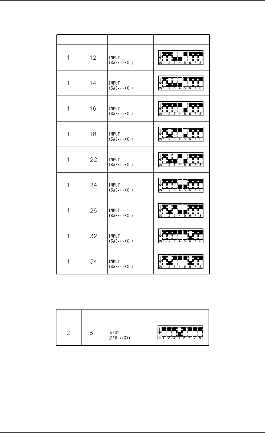
Setting of SDS Traverse Nodes (Option)
Ch. No.
Node No.
Node Type
Setting
Ch. No.
Node No.
Node Type
Setting
Table 3.6
Table 3.7
Setting of SDS Input Nodes (Main Body)