YSM10_Mainte_E.pdf - 第137页
6-5 6 How to replace consumable parts 3. Head unit If an operation failure occurs in the operation valve, blow valve, or shaft blow valve of the head unit, follow the steps below to replace the defective valve. n NOTE Be…
6-4
6
How to replace consumable parts
n
About leaf spring installation tool
When installing the nozzle leaf springs, use of the optional purchase part "leaf spring installation tool (P/
N:KGS-M8810-00X)" makes it possible to install the leaf springs more uniformly.
n
NOTE
If having this tool, it is recommended to install the leaf springs with this tool.
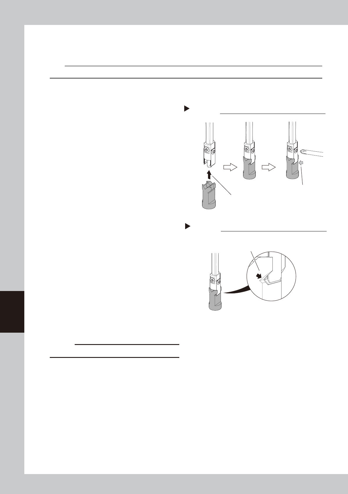
How to use the leaf spring installation tool
The following describes steps continued from Step 2 of "2.1 Replacing nozzle leaf springs".
3
Install new leaf springs temporarily.
Loosen the leaf spring mounting screw 1/4
turn from its fully closed position to install the
leaf springs temporarily.
4
Insert the tool.
Insert the tool into the nozzle shaft so that
the groove on the leaf spring installation tool
matches to the convex part of the leaf
spring.
Insert the tool all the way inside.
53604-KMG-00
5
Mount the leaf springs.
With the convex part of the leaf springs and
the groove on the tool held by finger,
tighten the leaf spring mounting screw with
a precision Phillips screwdriver to mount the
leaf springs.
6
Check the leaf spring installation
status.
Check that the groove on the tool is tightly
in contact with the convex part of the leaf
spring.
53605-KMG-00
7
Remove the tool.
8
Check the nozzle installation status.
1. Attach and detach the nozzle manually
several times to check that no looseness
is found.
2. Remove the square cloth.
c
CAUTION
Be sure to return the removed nozzle to its original head.
Insert the tool all the way
to the upper portion.
Leaf spring installation tool
Using the leaf spring installation tool
Step 4,5
Tighten the screw while
holding the convex part of
the leaf spring and the
groove on the tool.
Checking the leaf spring installation status
Step 6
The convex part of the leaf spring must be
tightly in contact with the groove on the tool.
6-5
6
How to replace consumable parts
3. Head unit
If an operation failure occurs in the operation valve, blow valve, or shaft blow valve of the head unit, follow
the steps below to replace the defective valve.
n
NOTE
Before replacing the valve, it is required to turn off the air supply and power off the machine.
3.1 Replacing the valves
1
Turn off the air supply and power
off the machine.
1. Close the software applications.
2. Power off the machine.
3. Turn the air supply/exhaust switch on the
lower left of the machine to the exhaust
side (EXT) and turn off the main air.
2
Prepare for work.
1. Move the head to an easy-to-work
position manually.
2.
Place a square cloth under the head unit
.
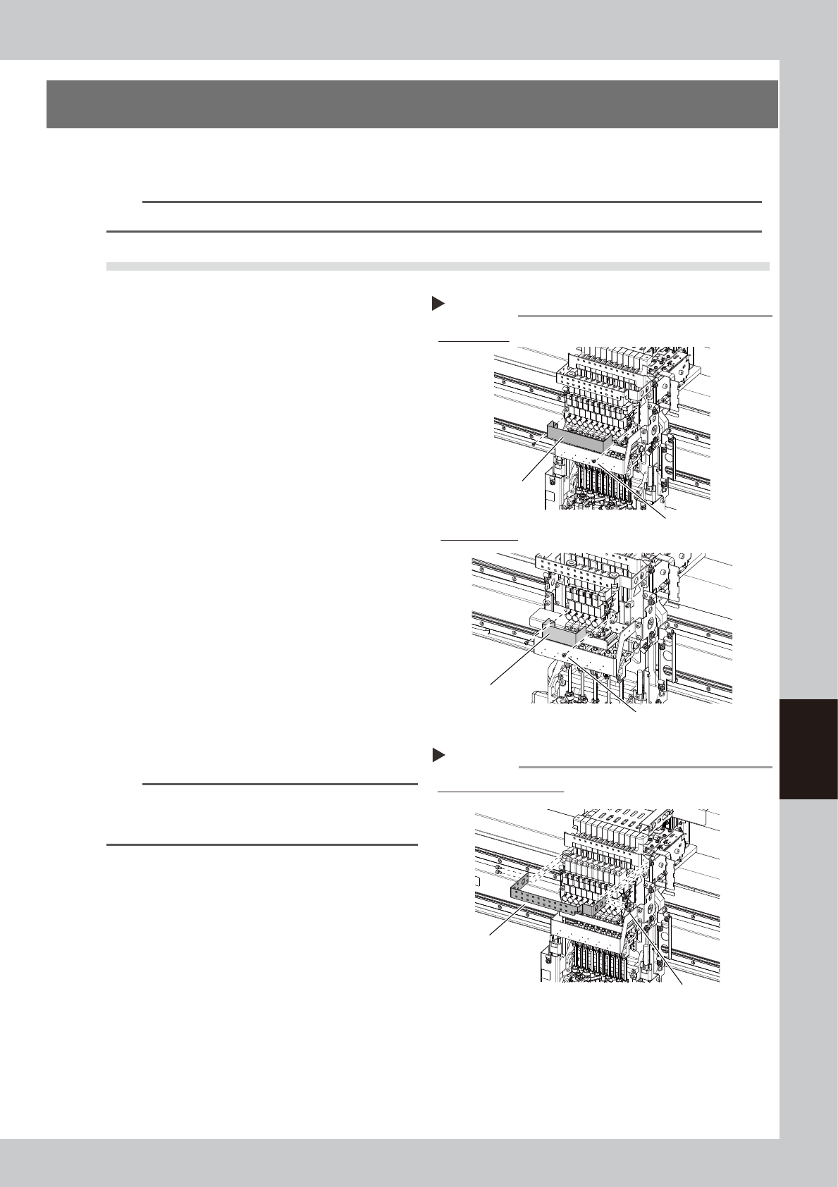
3
Remove the baffle plate. (Only
when replacing the operation valve)
Remove the baffle plate mounting screws (2
pcs.) with a Phillips screwdriver.
53606-KMG-00
4
Remove the head plate. (Only when
replacing the blow valve)
Remove the head plate mounting bolts (4
pcs.) with a hex wrench (3). The cables are
connected to the head plate. However,
these cables do not need to be
disconnected.
53607-KMG-00
n
NOTE
The attachment and detachment procedures of the
head plates for HM head unit and HM5 head unit are
the same.
Removing the baffle plate
Step 2
HM head unit
HM5 head unit
Baffle plate
Mounting screw (2 locations)
Baffle plate
Mounting screw (2 locations)
Step 3
Example of HM head unit
Removing the head plate
Head plate
Mounting bolt (4 locations)
6-6
6
How to replace consumable parts
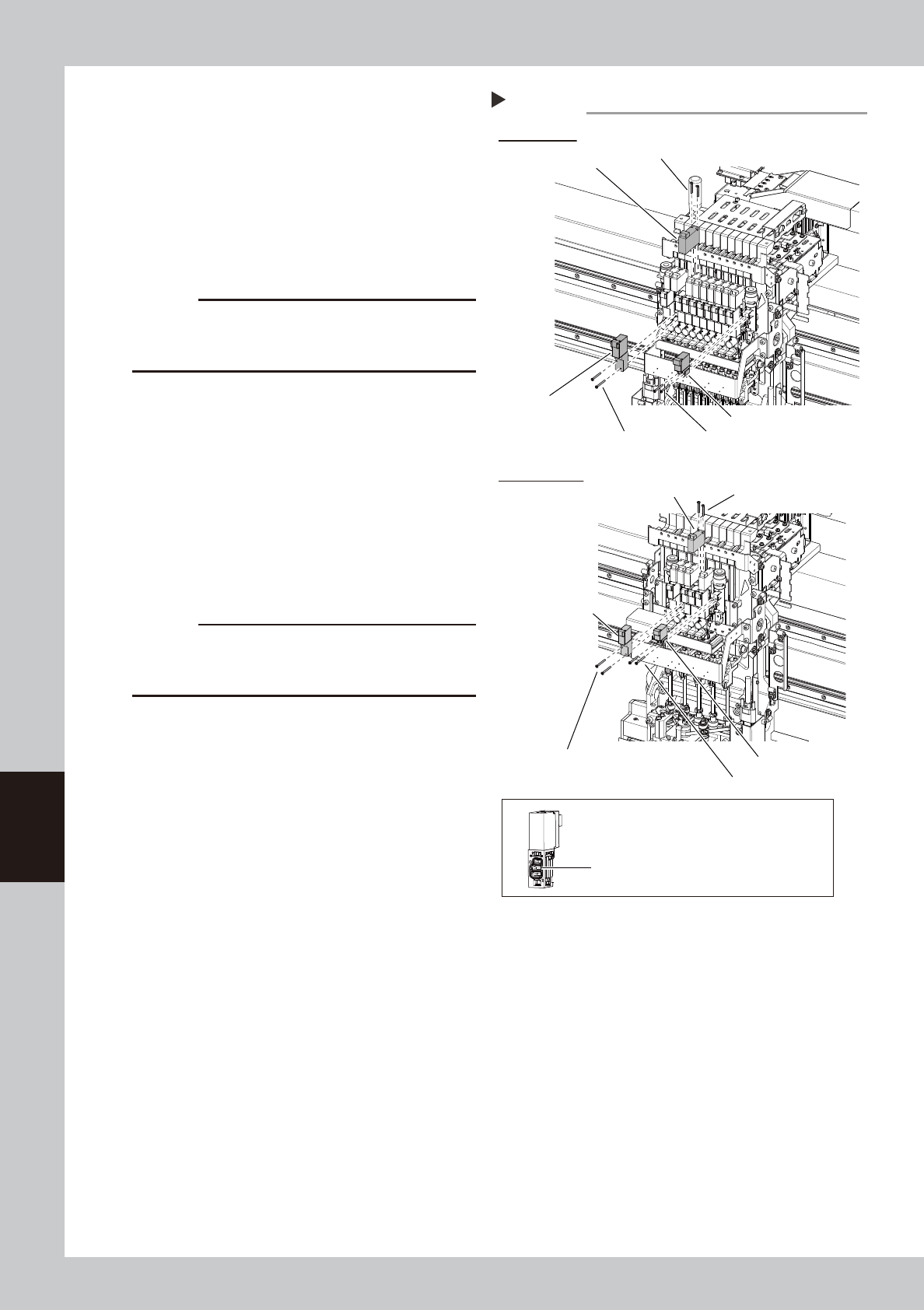
5
Disconnect the connector.
Disconnect the connector of the valve you
want to replace.
6
Replace the valve.
Remove the mounting screws (2 pcs.) of the
valve you want to replace with a precision
Phillips screwdriver, and then replace the
valve.
53608-KMG-00
c
CAUTION
The packing is attached to the back of the valve.
Replace the valve with a new one while carefully
checking the packing for dropping or catching.
7
Return the components to their
original positions.
1. Return the connector, head plate, and
baffle plate to their original positions.
2. Remove the square cloth under the head
unit.
8
Check the valve operation.
Turn on the supply air and main power, and
then check the operation of each valve on
the [Unit] - [Head] screen or [I/O] screen.
c
CAUTION
When checking the operation of the shaft blow valve
on the [I/O] screen, be sure to remove the nozzles from
all heads.
Step5
HM head unit
HM5 head unit
Blow valve
Blow valve
Mounting screw (2 locations)
Replacing the head valve
Shaft blow valve
Shaft blow valve
Mounting screw (2 locations)
Mounting screw (2 locations)
Mounting screw (2 locations)
Mounting screw (2 locations)
Operation valve
Operation valve
Mounting screw (2 locations)
The packing is attached to the back of the valve.
Be careful not to drop this packing.