YSM10_Mainte_E.pdf - 第143页
Appendix Appendix Contents 1. Specifications A-1 1.1 Air regulator unit A-1 1.2 Power connection terminals A-2 1.3 Connection between machines A-3 1.3.1 PREVIOUS INTERF ACE connector A-3 1.3.2 NEXT INTERF ACE connector A…
6-10
6
How to replace consumable parts
9
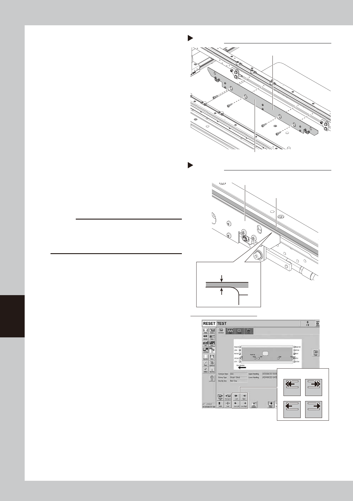
Mount the board clamp plate.
1. Fit the board clamp plate into its original
position and tighten the board clamp
plate mounting bolts with a hex wrench
(3).
2. Remove the square cloth on the push-up
plate.
53615-KMG-00
0
Check the belt rotating condition.
1. Make sure that the board clamp plate
top surface is approx. 0.5mm lower than
the belt upper surface.
2. Close the machine safety cover to
cancel the emeregency stop.
3. Press the [Conveyor In] button on the
[Unit] - [Conveyor] tab screen to turn on
the conveyor motor and check the belt
rotation.
4. If the conveyor belt rotation is uneven or
if the belt deflects, adjust the pulley
position that applies tension again.
54601-KMG-00
c
CAUTION
When the difference between the belt upper surface
and board clamp top surface is very little, the board
transfer error may occur easily. In this case, contact
YAMAHA or YAMAHA sales representatives.
Step 9
Mounting the board clamp plate
Board clamp plate
Board clamp plate mounting bolt
Step 10
Conveyor drive buttons
0.5 mm
Checking conveyor belt rotation
Left Right
Low Left
Check the belt rotating condition
Board clamp plate
Board clamp plate
Conveyor belt
Belt upper surface
Low Right

Appendix
Appendix
Contents
1. Specifications A-1
1.1 Air regulator unit A-1
1.2 Power connection terminals A-2
1.3 Connection between machines A-3
1.3.1 PREVIOUS INTERFACE connector A-3
1.3.2 NEXT INTERFACE connector A-4
2. Maintenance parts A-6
2.1 YSM10 main unit maintenance parts list A-6
2.2 sATS15 maintenance parts list A-10
A-1
Appendix
1. Specifications
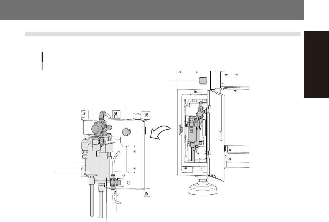
1.1 Air regulator unit
The air regulator unit of this machine is in the inside of the panel on the lower left of the front of the machine.
Supply air
connecting parti
Air valve for tape cutter
Air pressure regulator and pressure gauge
Air supply/exhaust switch
Air filter
Oil mist filter
Air pressure regulator
Digital pressure gauge
53A01-KMG-00
n
Supply air pressure
This is the pressure of the source air supplied to the machine. Before setting the air pressure with the air regulator, make
sure that this supply air pressure is in the following optimal range.
YSM10 : 0.45MPa to 0.70MPa
n
Digital pressure gauge
When within the normal range, the air pressure displays in green. When the air pressure is beyond the upper/lower limit
values, the air pressure displays in red and an error occurs.
n
Set pressure and air-down detection pressure
Set the following air pressures with the air pressure regulator on this machine.
Air pressure setting for machine : 0.40MPa (+/-0.01MPa)
Interlock set pressure : Lower limit 0.33MPa, Upper limit 0.45MPa
n
Air supply/shutoff switch (valve)
Turning this switch to the right (EXH) shuts off air supply and exhausts air that remains inside the machine.
n
Source air connector
Connect the supply air to the entrance of the air filter. Prepare an air hose with an inner diameter of at least 8mm having
a 40SH socket (Nitto Koki, or equivalent), and connect it to this connector. Use dry, clean air passed through an air filter.