YSM10_Mainte_E.pdf - 第77页
3-10 3 Periodic maintenance items 2.1 X-axis T his section explains the X-axis inspection, cleaning, and lubrication procedures. For details regarding lubrication points and the lubrication condition, see "Chapter 5…
3-9
3
Periodic maintenance items
2. Monthly inspection
This section mainly describes the procedures of inspecting, cleaning and lubricating the X, Y axes ball screw
and the guide. The inspection items and cautions of X, Y axes are given below.
n
Inspection items
1. Any foreign matter adhering to the ball screws and linear guides?
Check if any fallen chips have adhered to the X and Y axis ball screws and/or X, Y and W axis linear guides.
2. Do the ball screws and linear guides have the correct amount of grease?
Check if grease has flowed off or splattered in the air failing to adhere. Also check if grease has discolored or hardened.
e
3. Any abnormal sounds from the ball screws?
Press the emergency stop button. Push the X-axis or Y-axis manually to check that they move smoothly and no abnormal
sounds are heard.
Countermeasures
1. Ball screws and linear guides may be damaged when chips and other material bite into them. If chips are adhering,
wipe them off along with the grease or remove with tweezers, etc.
2. Apply grease while referring “Cleaning and lubrication” described later on.
3. Consult your YAMAHA sales office or representative when abnormal sounds occur even after trying the
countermeasures in the above steps 1 and 2.
n
Cautions
w
WARNING
THE HEAD UNIT OF THE MACHINE CONTAINS PARTS GENERATING STRONG MAGNETIC FIELDS. GREAT CARE SHOULD BE
TAKEN WHEN A PART OF YOUR BODY IS PUT INSIDE THE MACHINE FOR THE MAINTENANCE WORK. CAUTIONS REGARDING
FERROMAGNETIC FIELDS ARE DESCRIBED IN THE SECTION, "SAFETY INSTRUCTIONS", AT THE BEGINNING OF THIS
DOCUMENT. ALWAYS THOROUGHLY READ THIS SECTION TO FULLY UNDERSTAND ITS CONTENTS.
c
CAUTION
If abnormal noise is emitted from the ball screw or linear guide of each axis ball screw or linear guide, then contact
our sales representative for assistance. Disassembly and cleaning of the ball screw or linear guide by the user will void
the warranty.
c
CAUTION
When performing the cleaning and greasing work, use square cloth to prevent parts from being lost.
c
CAUTION
When handling grease, read the safety precautions stated in "Safety instructions" and "2.3.2 Lubricating tools and
grease" in Chapter 1.
3-10
3
Periodic maintenance items
2.1 X-axis
This section explains the X-axis inspection, cleaning, and lubrication procedures. For details regarding
lubrication points and the lubrication condition, see "Chapter 5 Lubrication points and schedule". The user
must provide the grease gun (standard nozzle) and the prescribed grease (NSL).
n
NOTE
The procedure and the lubrication points of HM head unit are described as example. Those of HM5 head unit are also the same.
2.1.1 Cleaning and lubricating the X-axis ball screw
1
Prepare for the work.
e
1. Press the emergency stop button to open
the machine safety cover.
2. Grasp the carrying handle to move the
head unit forward.
3.
Place a square cloth under the head unit
.
53312-KMG-00
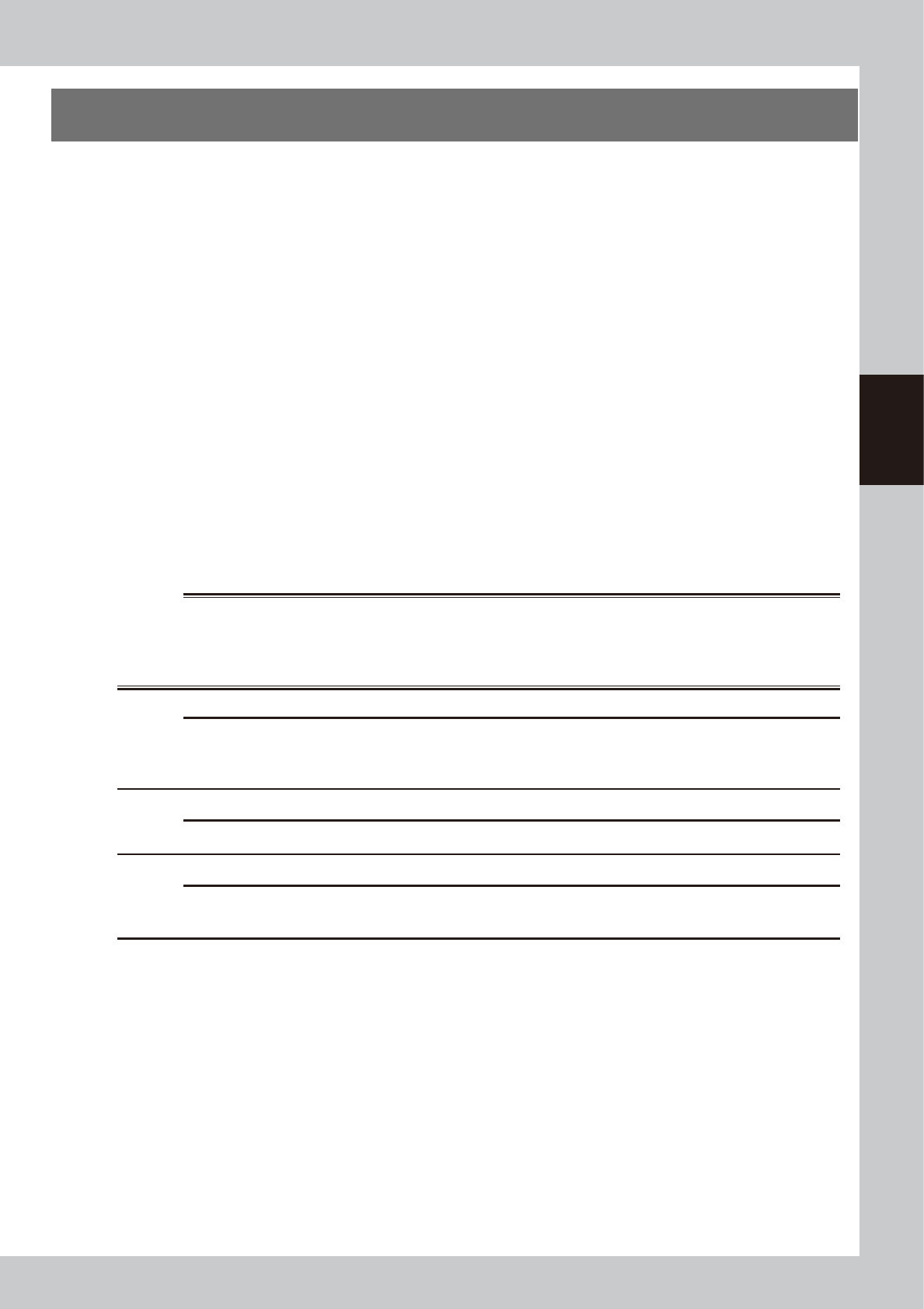
2
Remove the anti grease splatter
cover.
1. Remove 2 mounting screws on the left
side of the anti grease splatter cover with
a phillips screwdriver.
2. Loosen 2 mounting screws on the right
side of the cover. It is not necessary to
remover them.
3.
Grasp the carrying handle to move the
head to the right. Pull out the anti grease
splatter cover toward the left to remove it.
TIP
Re
attaching the X-axis ant grease splatter cover by
reversing the above removal procedure.
53313-KMG-00
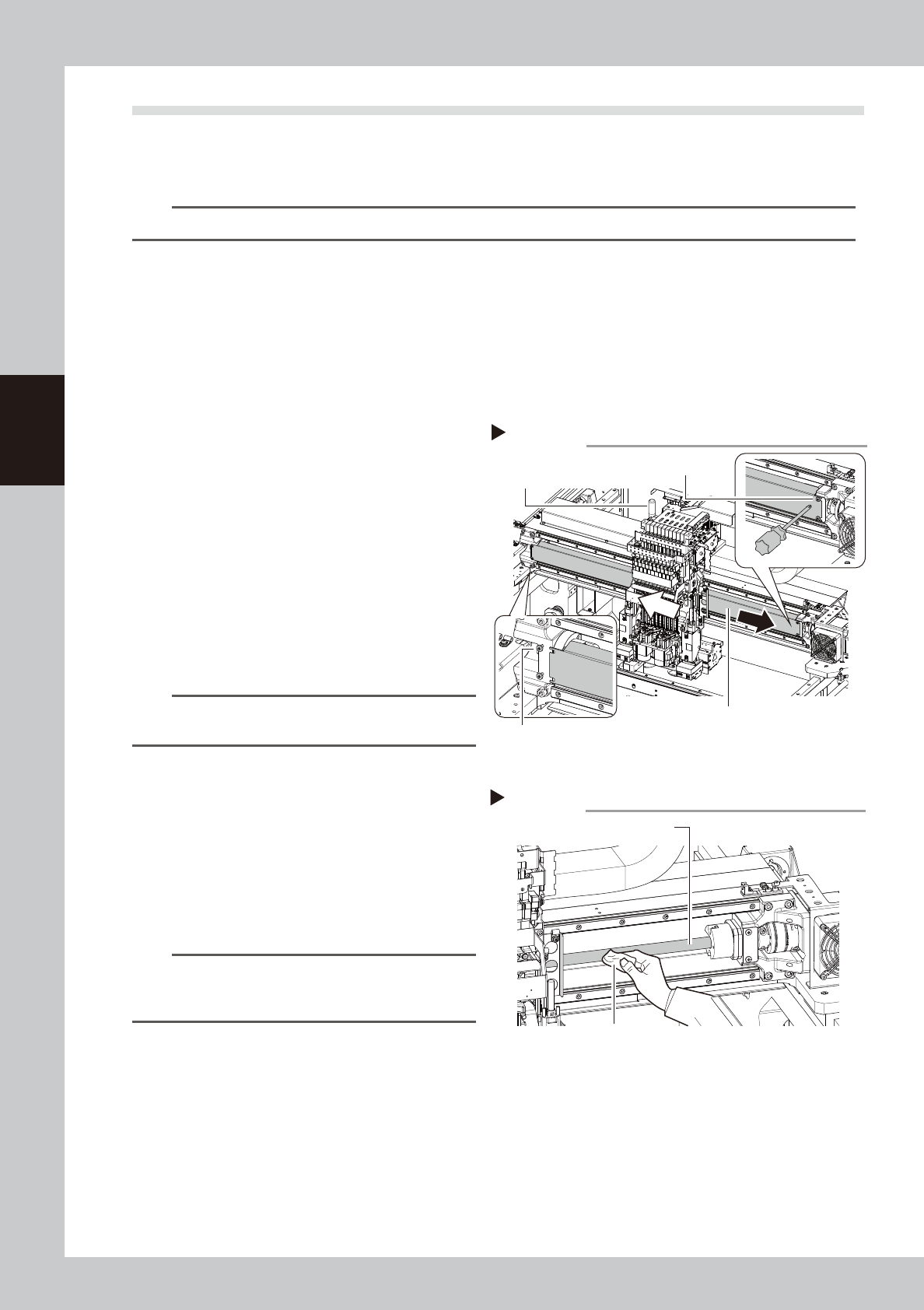
3
Clean the ball screws.
1. Move the head unit to one end.
2. Wipe away the old grease and dirt from
the ball screw with a lint-free cloth or
paper towel (for clean room use).
3. Move the head unit to the opposite end,
then wipe the opposite-side ball screw.
n
NOTE
When cleaning the ball screw, carefully clean its
groove area as well. Be sure that the cloth, etc., being
used to clean the ball screw does not produce lint, etc.
53314-KMG-00
Removing anti grease splatter cover
Step 2
Anti grease splatter cover
Cover mounting screws
Cover mounting screws
Carrying handle
Step 3
Cleaning the ball screw
Cloth
Ball screw
3-11
3
Periodic maintenance items
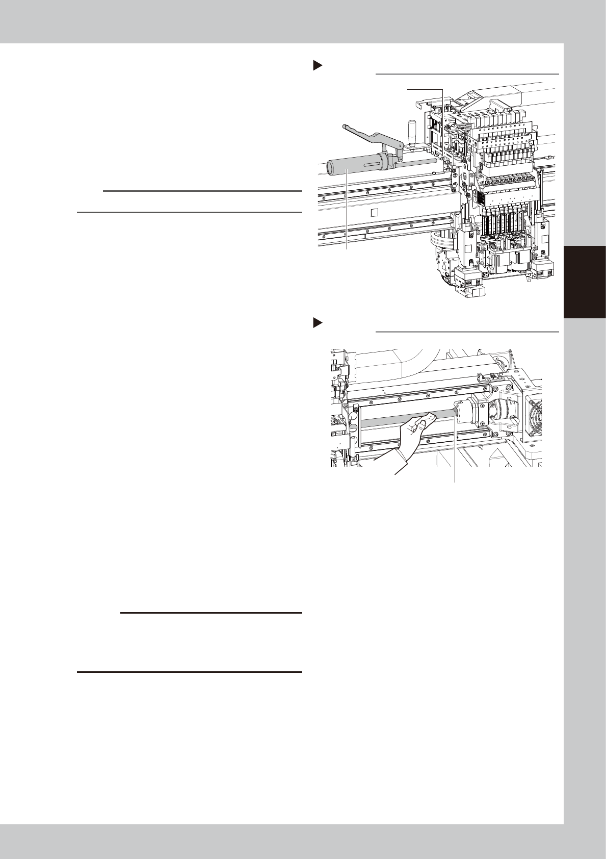
4
Inject the grease.
1. As shown in the figure on the right, move
the head unit to the right to see the
grease nipple.
2. The grease nipple at the center of those
aligned at 3 locations is the ball screw
nipple. Use a grease gun (standard type)
to inject the prescribed grease at the
grease nipple.
n
NOTE
Inject until the grease begins to seep out from the gap.
5
Wipe off the excess grease.
1. Grasp the carrying handle and move the
head unit to the left.
2. Wipe all excess grease from the ball
screw and the ball screw end faces.
3. Move the head unit to the opposite end
and wipe all excess grease from the
opposite-end ball screw and the ball
screw end faces.
53315-KMG-00
6
Perform a warm-up.
1. Remove the square cloth.
2. Reattach the anti grease splatter cover.
3. Close the machine safety cover and
cancel the emergency stop.
4. Press the [Warm Up] button on the
"Setup" screen to open the "Warm Up"
screen. Perform the warm-up operation
for approx. 8 minutes.
e
7
Check the grease condition.
1. After stopping the warm-up, press the
emergency stop button to open the
machine safety cover.
2. Remove the anti grease splatter cover
and wipe off grease which has collected
on the ball screw and the ball screw end
faces.
c
CAUTION
Repeat Steps 6 and 7 until grease accumulations no
longer occur. Beginning production with grease
accumulations present could cause the grease to
spatter.
8
Attach the anti grease splatter
cover.
Step 4
Grease nipple (center)
Grease gun (standard type)
Applying grease
Step 5
Wiping off the excess grease
Excess grease