YS12调整.pdf - 第12页
Service Engineer Service I nformati on SI080 4004 E-000 = YS12 , YG12: Procedure for adjustmen t after installa tion of the mach ine 12/60 4. Set the Glass board on the convey or. Click on the [Board Clamp] button on the…
Service Engineer
Service Information
SI0804004E-000 = YS12, YG12: Procedure for adjustment after installation of the machine
11/60
4.4.How to adjust the PCB height
“PCB height” is the reference height for the head to mount components, and is automatically
measured according to the changes in the vacuum pressure of the nozzle when it contacts the
board surface. The “Vacuum Level“ needs to be adjusted before measuring the PCB height.
Measure the four points on the top surface of the aluminum frame of the Glass QFP, and save the
height of the lowest point as the “PCB height”.
<Tools used for adjustment>
KHN-M7720-A0X NOZZLE 302A ASSY.
Nozzle for chip
components
(Standard set)
KHY-M7730-A0X NOZZLE 313A ASSY.
Nozzle for chip
components
(Narrow pitch set)
Use either of the
nozzle
KM0-M8810-40X GLASS PCB ASSY.4 ACP glass board
KM0-M8810-10X GLASS PCB ASSY.1 AMF glass board
Use either of the board
Table 6
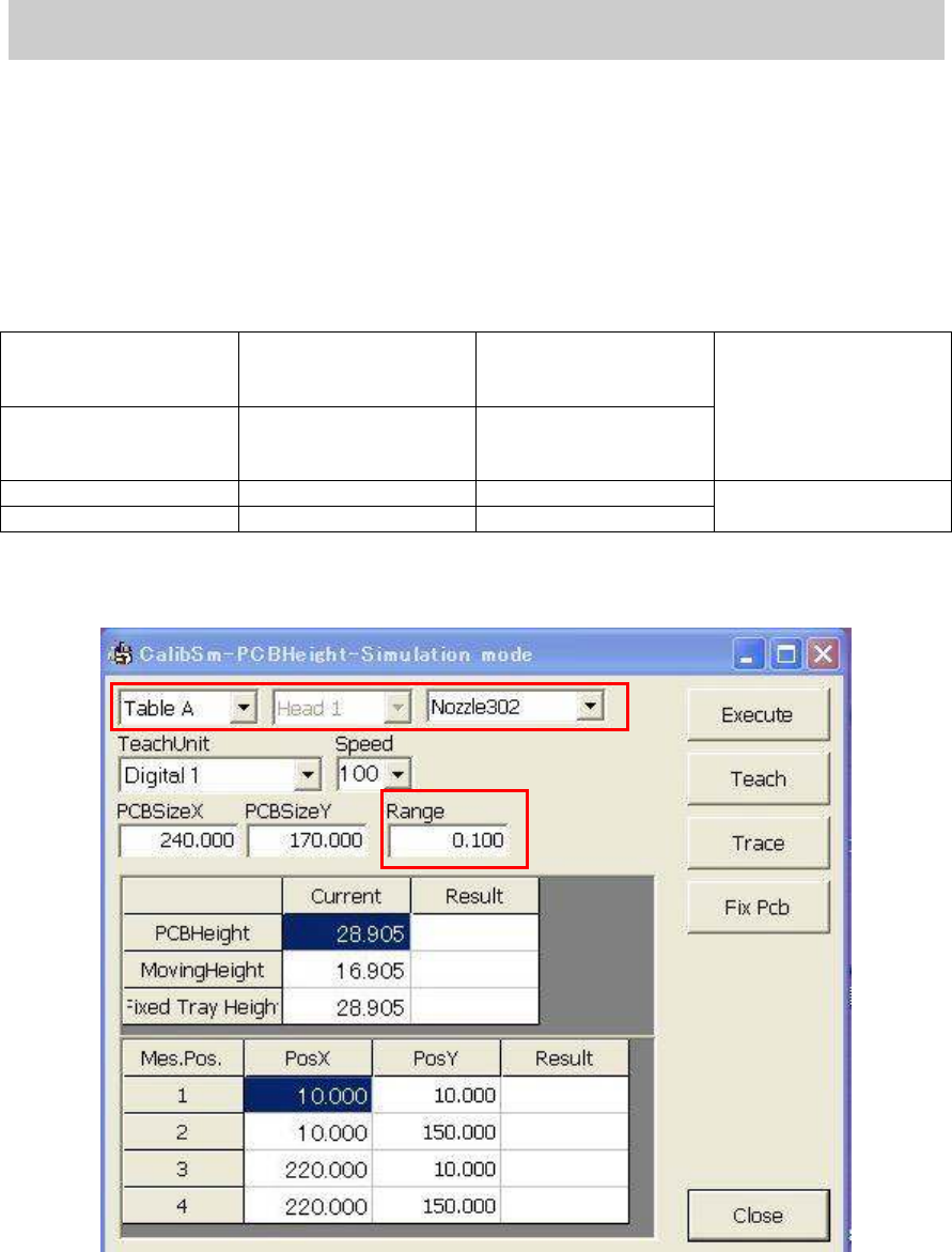
1. Click on the [PCB height] button on the main screen of the CalibSm.
Figure 8
2. Check the nozzle to be used.
Select “Nozzle 302A” or “Nozzle 313” as the PCB height is measured by the difference of the
vacuum pressure of the nozzle.
3. Check the value in the “Range” field.
The four points on the aluminum frame of the glass board are measured and the difference
between the maximum and minimum value is checked automatically. Please make sure that
the value in the “Range” field (standard value) is “0.100”.
Service Engineer
Service Information
SI0804004E-000 = YS12, YG12: Procedure for adjustment after installation of the machine
12/60
4. Set the Glass board on the conveyor.
Click on the [Board Clamp] button on the “Conveyor” tab on the “Unit screen in order to clamp
the board.
Figure 9
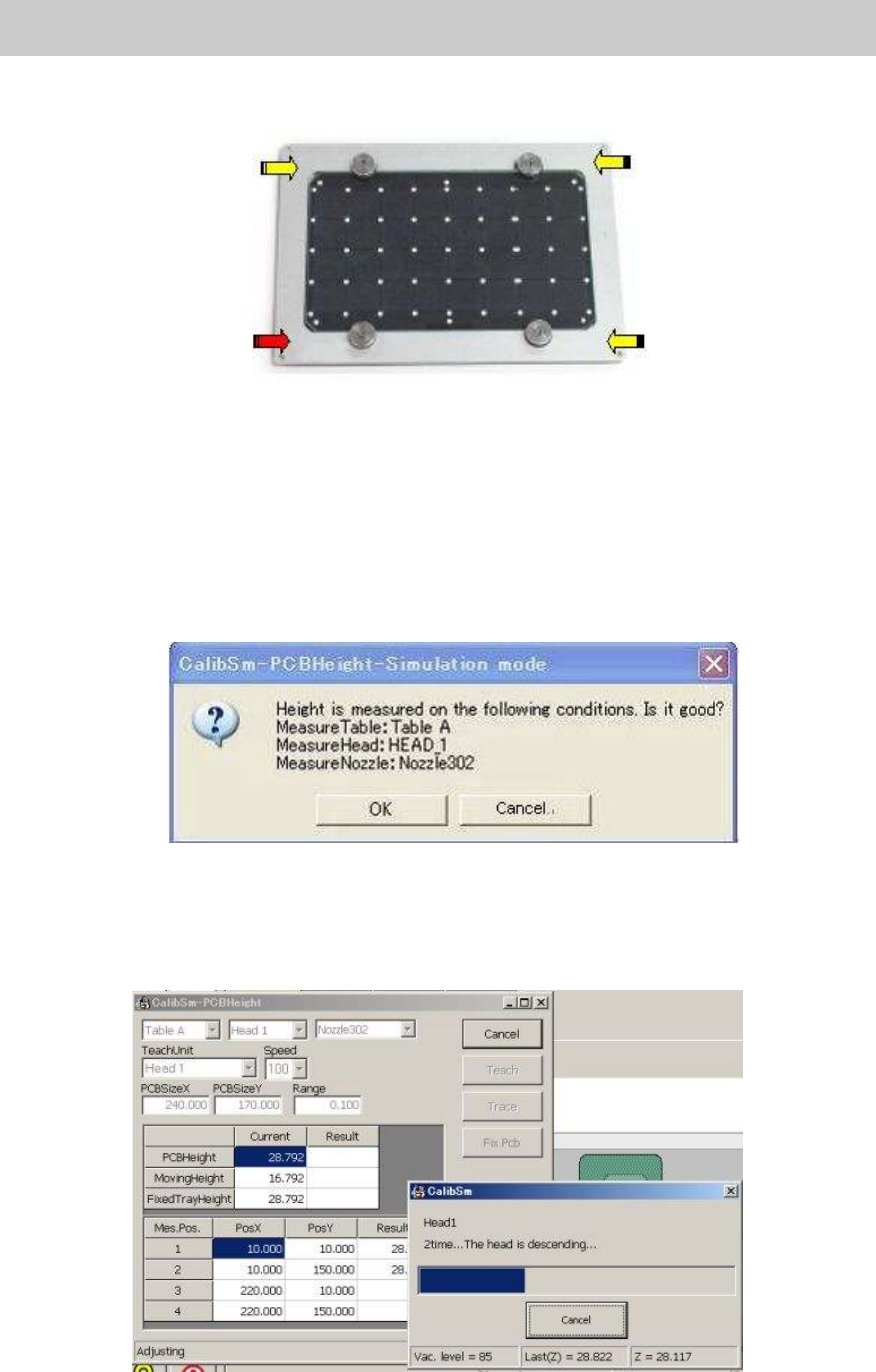
5. Move the head to the measurement position.
Select “Head 1“ from the dropdown list of the “TeachUnit” item, and then click on the [Trace]
button to move the Head 1 to the measurement position on the upper surface of the aluminum
frame (at the lower left).
6. Click on the [Execute] button.
Check if the Head has moved to the position where the nozzle of the Head 1 descends (at the
lower left of the aluminum frame of the glass board), and click on the [Execute] button.
When the message dialog box (See Figure 10) appears, check the message and click on the
[OK] button.
Figure 10
<If you click on the [Execute] button…>
The four points on the top surface of the aluminum frame of the Glass QFP are measured, and
the height of the lowest point is saved as the “PCB height” automatically.
Figure 11
Service Engineer
Service Information
SI0804004E-000 = YS12, YG12: Procedure for adjustment after installation of the machine
13/60
Figure 12
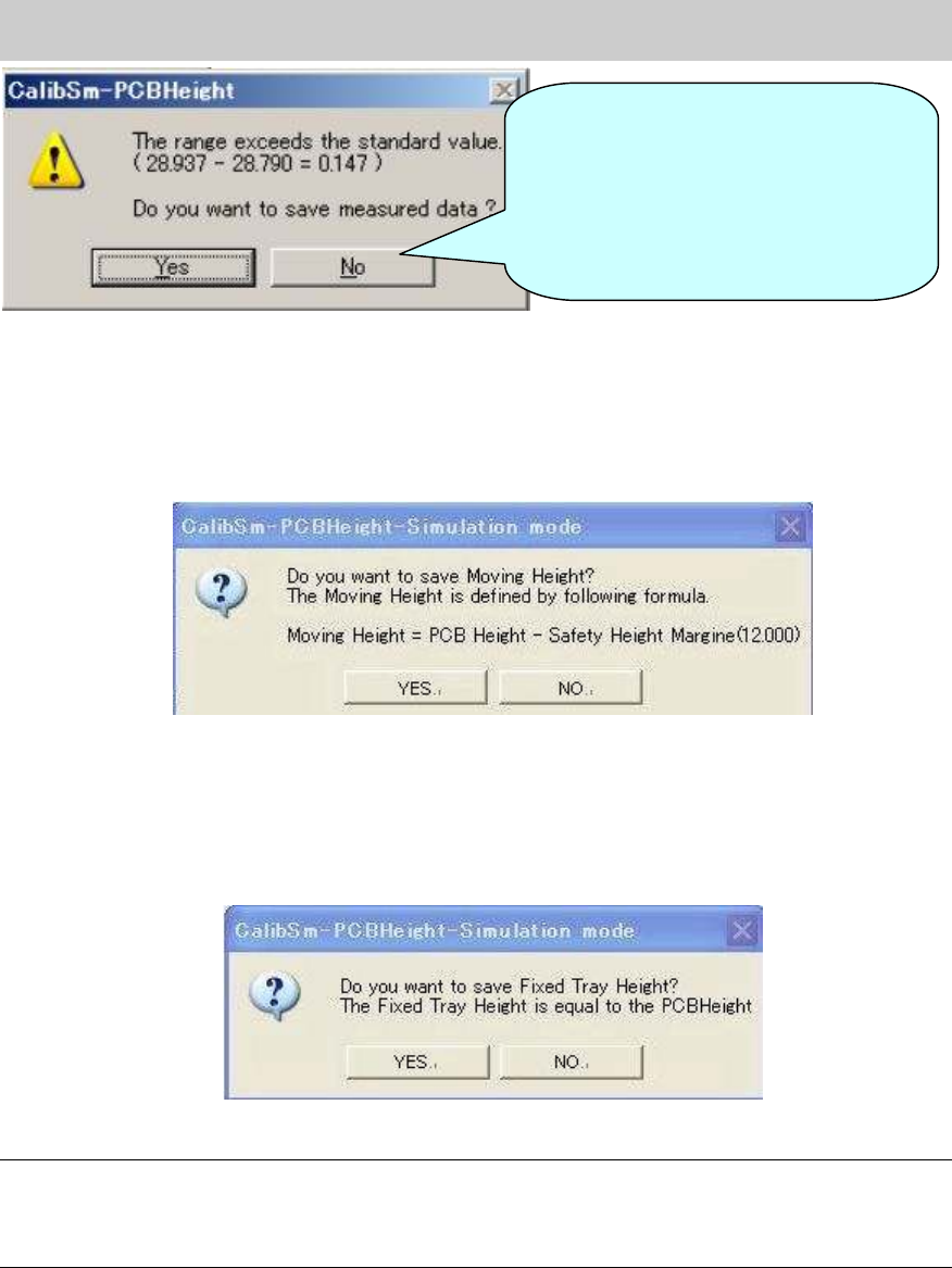
7. Check the value in the “Moving Height” field.
After saving the data of the “PCB Height”, the message appears asking you to save the
“Moving Height”. As the value is calculated automatically, please save the data without change
except for when the special setting is set.
Figure 13
8. Check the value in the “Fixed Tray Height” field.
After saving the data of the “Moving Height”, the message appears asking you to save the
“Fixed Tray Height”. As the value is calculated automatically, please save the data without
change except for when the special setting is set.
Figure 14
Note:
If the 302A nozzle, 313A nozzle and 309A nozzle cannot be prepared, please click on the
[Measuring Height] button on the CalibSm main menu and select “Manual” item to measure the
height manually.
If the difference between the
maximum value and the minimum
value of the PCB height exceeds the
specified value, the message is
displayed on the dialog box. Please
check if the board is clamped properly
and perform adjustment again.