YS12调整.pdf - 第60页
Service Engineer Service I nformati on SI080 4004 E-000 = YS12 , YG12: Procedure for adjustmen t after installa tion of the mach ine 60/60 10.Change the settings back to the customer ’ s setting and confirm the setting […
Service Engineer
Service Information
SI0804004E-000 = YS12, YG12: Procedure for adjustment after installation of the machine
58/60
9. Items to be checked after accuracy adjustment
9.1.Check if the board is transferred properly from the upstream machine to the
downstream machine
1. Output request signal to the upstream machine, and check the signal sent from the
downstream machine on the “I/O” tab on the “Unit” screen,
2. Change the setting of the “Conveyor Spec” to “Line”.
Click on the [Edit] button on the “Sequence” tab on the “Board” screen, and then select “Skip”
from the “Mount item” in order to transfer a board from the upstream machine to the
downstream machine.
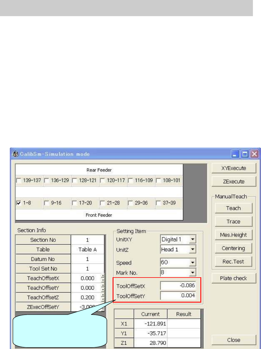
9.2.Check the pickup position of the feeder
Click on the [FeederPos] button on the main screen of the CalibSm and check the pickup
position of the feeder.
Figure 80
Input the compensation value
(Offset value) of the tool to be
used before adjustment.
Service Engineer
Service Information
SI0804004E-000 = YS12, YG12: Procedure for adjustment after installation of the machine
59/60
9.3. Check the operation of the blow station
Click on the [Cleaning Blow] button on the “Head” tab on the “Unit” screen to check the
operation of the blow station.
Figure 81
9.4. Check the “PCB origin”
1. Set a board on the mounting position.
Set the coordinate of the PCB origin XY to 0.00 and move the camera to the position.
2. Click on the [Position] button on the main screen of the CalibSm and check the values of the
“Edge Clamp”.
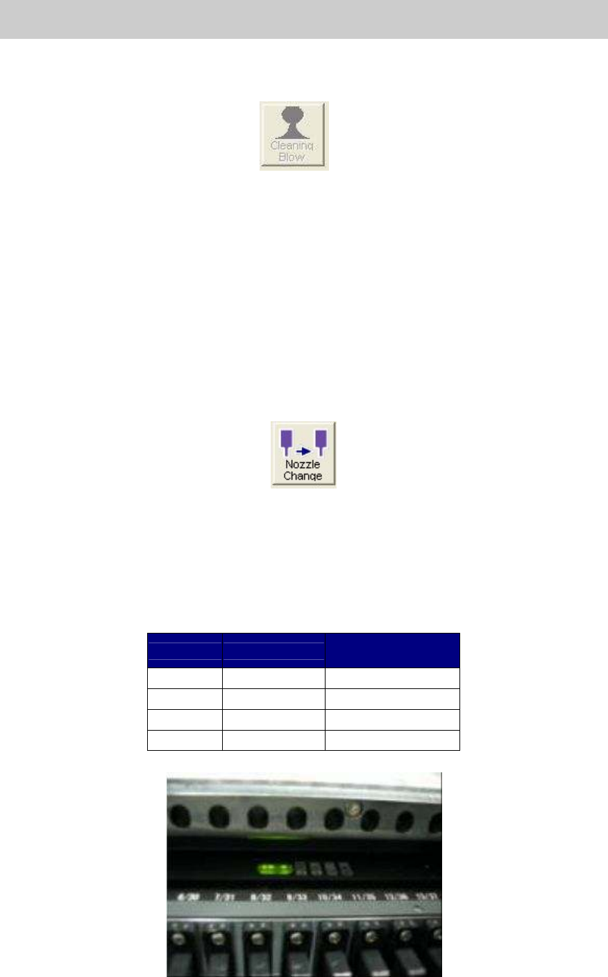
9.5. Check the operation of the “Nozzle change” function (Option)
1. Click on the [Nozzle Change] buttons on the “Head” tab on the “Unit” screen to check the
operation of the “Nozzle Check” function.
2. Click on the [ANC] button on the main screen of the CalibSm, and select “Test Change
Nozzle” to check the adjustment result.
Figure 82
9.6. Check the operation of the feeder exchange carriage (Option)
1. Check if all the carriage can be installed into the machine or be released from the machine
without hitch.
2. Check if the LED of the carriage lights up when the carriage is fully installed into the correct
position of the machine.
Indication
LED
Normal lighting
condition
+24V Green LED Lights up
+5V Green LED Lights up
SC Orange LED Blinks (1 sec.)
MON Green LED Lights up
Table 31
Figure 83

Service Engineer
Service Information
SI0804004E-000 = YS12, YG12: Procedure for adjustment after installation of the machine
60/60
10.Change the settings back to the customer’s setting and
confirm the setting
[Change the machine settings back to the customer’s setting]
When completing the mounting accuracy adjustment, change the settings for adjustment back to
the customer’s settings.
- Conveyor Spec : Change from “Demo Fixed” to “Line”
- Adjust mode : Change from “AdjustMode1” to “None”
- Mount Info. Mode : Change from “V30. Extended” to “V2.0 Compatible”
- Setting for “FAMF” screen : Disable the FAMF function.
Change the “Measuring Tool” item from “PCB” to “Station”.
Click on the “SW Version” button on the “Setup” screen to display
the “Version” screen, and close it without punching in the
password.
- Head Specification : Check if any nozzles that the customer does not own are
registered.
[Check the machine setting]
Please confirm the desired setting with the customer before changing the settings.
- Head Offset : Select “ManualNzlChg” or “Fixed Nozzle” from the dropdown list of
the “HeadType”.
- Board data type : Check if the customer’s desired board data type is selected from
the dropdown list of “File Format”.
- Board data to load : Check the location of the data to load the board data from.
- Database path : Check the database path on the “Database Utility” screen.
- Check “The timing to set from database all (parts and mark)” on the “Database Utility” screen.
- Click on the [Editor] button and check the ”File Type” in the “Board data select” dialog.
11.Data backup
After checking all the settings, make backup copies of the adjusted system data for giving to the
customer and for bringing back.
Save the other ACP adjustment data (FAMF data) to bring back.
Note:
Some customers put restrictions on taking out the data. Please confirm if the data can be brought
back with the customer.