YS12调整.pdf - 第49页
Service Engineer Service I nformati on SI080 4004 E-000 = YS12 , YG12: Procedure for adjustmen t after installa tion of the mach ine 49/60 7.3.6. Setting for operation and measurement (FAMF) This sec tion describes how t…
Service Engineer
Service Information
SI0804004E-000 = YS12, YG12: Procedure for adjustment after installation of the machine
48/60
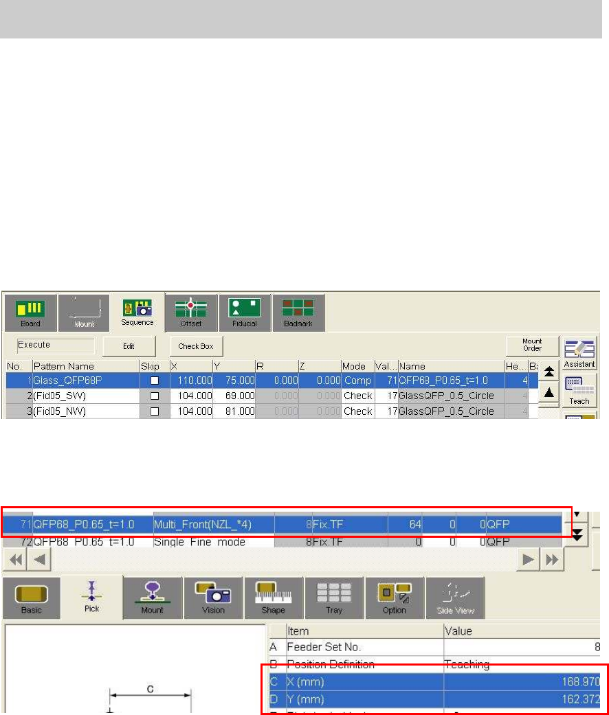
7.3.5. Perform “Teaching” for the components pickup position
In FAMF adjustment, the component (Glass QFP) is picked up from the mounting position on the
station, then recognized and mounted on the station again.
Please perform teaching for the coordinate of the mounting position as the component pickup
position.
1. Check the parts information
Basically the settings do not need to be changed.
(Check if “Fix.TF” is selected as “Feeder Type”)
2. Move the camera to the coordinate of the component mounting position by trace.
Select No.1 from the table on the “Sequence” tab on the “Board” screen.
Figure 67
3. Perform teaching for the coordinate of the component pickup position.
Perform teaching for the X, Y coordinates of the Parts information No.71 on the “Pick” tab on
the “Parts” screen with the camera at the mounting position.
Figure 68
Service Engineer
Service Information
SI0804004E-000 = YS12, YG12: Procedure for adjustment after installation of the machine
49/60
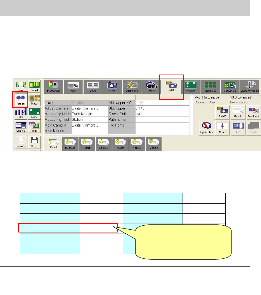
7.3.6. Setting for operation and measurement (FAMF)
This section describes how to set the settings for FAMF adjustment for the multi camera.
1. Display the FAMF setting screen.
Click on the [Monitor] button and display the “FAMF” tab.
*Please refer to “5.1.3. How to display the FAMF screen” for how to display the FAMF screen.
Figure 69
2. Check the settings
The multi cameras used for adjustment mounted on the front side is Digital 5, and the one on
the rear side is Digital 6.
Please check the setting referring to Table 24.
Table Table A Std. Upper XY 0.030
Adjust camera Digital 5 Std. Upper R 0.120
Measuring Mode
Each Nozzle R axis Calib Use
Measuring Tool Station
Main Camera Digital 3
Main Nozzle 1
*Note1
Table 24
Note:
The main nozzle changes depends on the specification of the machine.
- When the “Standard” set is used (30* series nozzle): 1 (301A nozzle)
- “When the “Narrow pitch” set is used: (31* series nozzle): 2 (312A nozzle).
[Items to be adjusted]
Digital 5_Head 4,8_Nozzle 304_”Precision Each Nozzle” parameter
Digital 5_Head 4,8_”Precision Rotation” Parameter
[Caution]
Please change the setting to
from “Station” to “PCB”
after adjustment.
Service Engineer
Service Information
SI0804004E-000 = YS12, YG12: Procedure for adjustment after installation of the machine
50/60
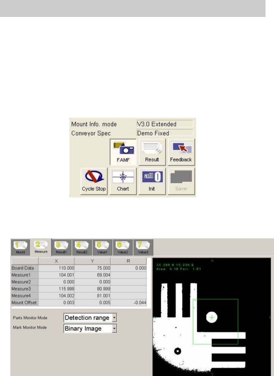
7.3.7. Start operation and measurement
1. Click on the [FAMF] button.
Without clicking on the button, the function to check the mounting state does not work.
2. Click on the [Init] button before starting operation.
Click on the [Init] button for initialization just in case the previous measurement data still
remains.
3. Click on the [Cycle Stop] button.
As “Demo Fixed” is selected from “Conveyor Spec”,
without clicking on the button, the
mounting operation will be repeated again and again.
Figure 70
4. Click on the [Start] button on the machine to start operation.
* The recognition result of the each mounting can be checked on the “Measure 2” tab.
Please keep an eye on the value of the “Mount Offset” during operation.
Figure 71