YS12调整.pdf - 第8页
Service Engineer Service I nformati on SI080 4004 E-000 = YS12 , YG12: Procedure for adjustmen t after installa tion of the mach ine 8/60 4. A djustment s (Prep aration for the m ounting adjustment) After installing the …
Service Engineer
Service Information
SI0804004E-000 = YS12, YG12: Procedure for adjustment after installation of the machine
7/60
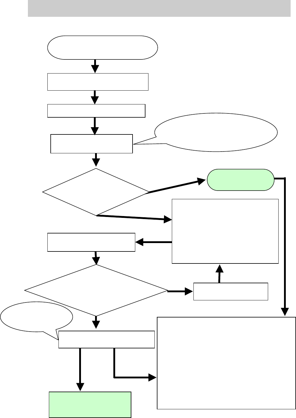
<The basic flow of the “Mounting adjustment” after installing the machine>
Figure 4
Prepare for the accuracy check of
the reference nozzle with ACP.
Perform accuracy check of the
r
eference nozzle with ACP
Please refer to “6.1. The workflow
when
“AMF Index” falls below 1.000”
<Readjustment of the items related
to mounting accuracy>
- Camera scale of the fiducial camera
- The camera scale of the scan camera
- Positioning of the scan camera
-Head Offset XY
<Check the other functions>
- Check if the board is transferred from the
upstream machine to the down stream
machine smoothly.
- Check the pickup position of the feeder plate.
- Check the operation of the blow station.
- Check the “PCB origin”.
- Check the vacuum level.
- Check the operation of the “Nozzle change”
function (Option)
- Check the operation of the feeder exchange
carriage (Option)
Perform adjustment of the
reference
nozzle with ACP
Check the value of “AMF
Index” after adjustment.
Does the value meet the
specification?
Check the value of AMF Index
Complete
mounting
adjustment
Save the data as the accuracy
before adjustment after
relocation of the machine.
Save the value as
the accuracy after
adjustment
.
Investigate the cause of
the problem
NG
OK
Does the value of
AMF Index meet
the specification?
Save the measured result
of the mounting accuracy
Save the result of the mounting
accuracy after adjustment.
Check the accuracy of the
multi camera and perform
adjustment (Option)
NG
Service Engineer
Service Information
SI0804004E-000 = YS12, YG12: Procedure for adjustment after installation of the machine
8/60
4. Adjustments (Preparation for the mounting adjustment)
After installing the machine and performing safety check, turn on the power and the air supply in
order to start up the machine.
This section describes the works and adjustments need to be done before performing mounting
adjustment (by ACP) after starting up the machine.
4.1. System data backup
Note:
The system data is basically backed up at the factory when the adjustment is performed after
assembling the machine. However, in case some changes of the settings are made before
shipment of the machine (ex. When you perform checking with the customer if the machine meets
the specifications.), the changes may not be saved. Please make a backup copy of the system
data before adjustment.
(* Please refer to the Operation manual for how to backup the data.)
4.2. Dual drive offset adjustmet for the Y-axis
Y-axes are driven by two motors. The “Return-to-origin” motion is performed with the Y1 axis, and
the pulse indicates the position of the Y2 axis when the Y1 is at the original position.
The Y2-axis moves in synchronization with the Y1 axis, and the deviation of the motion between
the two axes is monitored by pulse. The deviation due to the relocation of the machine can be
corrected by performing “Y-axis dual drive adjustment” in order to increase the accuracy of the
monitoring.
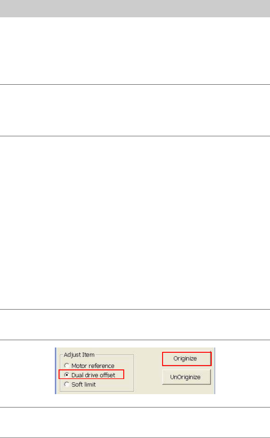
1. Click on the [Axis] button on the CalibSm main menu to display “Axis” screen, then select
“Dual drive offset” from the “Adjust Item”.
After selecting “Dual Drive Offset”, fill in the current value of the “Dual Offset” on the check
sheet.
2. Click on the [Originize] button to check the measured value.
3. Check the dual drive offset value and save the data.
Make sure that the offset value of the Y2 axis (Pulse) falls within the specification, then save
the data.
Fill in the current value (Current) and the measured value (Result) on the check sheet.
<Specification>: 63000 - 65000
Note:
Even though the value falls within specification, if the value (pulse) after adjustment is more than
1000 (pulse) larger or smaller compare to the value before adjustment, please renew the data.
If the variation is within 1000 (pulse), the adjustment does not need to be performed.
Figure 5
Caution:
- If the result does not fall within specification, please investigate the possible cause of the
problem. (Abnormal level of the base, deviation of the coupling, abnormal motor, and so on)
- When replacing the coupling or the motor, please adjust the pulse to 64000 +- 300.
Service Engineer
Service Information
SI0804004E-000 = YS12, YG12: Procedure for adjustment after installation of the machine
9/60
4.3. How to check the paralellism and the width of the conveyor
After making sure that the X-Axis and the reference conveyor are parallel to each other, check the
parallelism between the reference conveyor and the movable conveyor, and the reference of the
conveyor width.
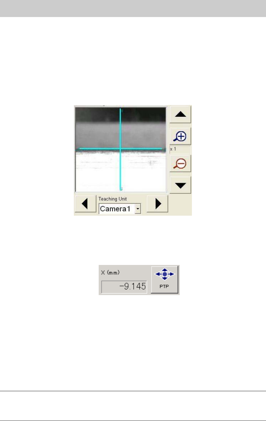
4.3.1. Check the parallelism of the reference conveyor
1. Obtain the coordinate of the Y-axis at the edge face of the reference conveyor near the main
stopper by performing teaching with the fiducial camera.
Fill in the coordinate of the Y-axis on the check sheet.
Figure 6
2. Move the X-axis 400mm to the plus (+) direction.
Click on the [PTP] button and move the X-axis 400mm to the plus (+) direction from the
current position by entering the value in the input field.
(If the PCB transport direction is from left to right, move the axis 400mm to the minus (-)
direction.)
Figure 7
3. Obtain the coordinate of the Y-Axis again after moving the X-axis.
Obtain the coordinate of the Y-Axis again after moving the X-axis by performing teaching for
the same Y-axis coordinate obtained in Procedure 1.
Fill in the coordinate of the Y-axis on the check sheet.
4. Check the difference of the Y-axis coordinates.
Calculate the difference between the Y-axis coordinate obtained in Procedure 1 and the
Y-axis coordinate obtained after moving the X-axis.
Fill in the value on the check sheet.
<Specification>: The difference in the Y direction is less than 0.05mm
Note:
If the result does not fall within specification, please check if the reference conveyor and the
movable conveyor are parallel to each other and the conveyor is not interfere with the cover of the
machine.