YS12调整.pdf - 第57页
Service Engineer Service I nformati on SI080 4004 E-000 = YS12 , YG12: Procedure for adjustmen t after installa tion of the mach ine 57/60 W hen the m achine is equipped with only one m ulti cam era, whichever side the c…
Service Engineer
Service Information
SI0804004E-000 = YS12, YG12: Procedure for adjustment after installation of the machine
56/60
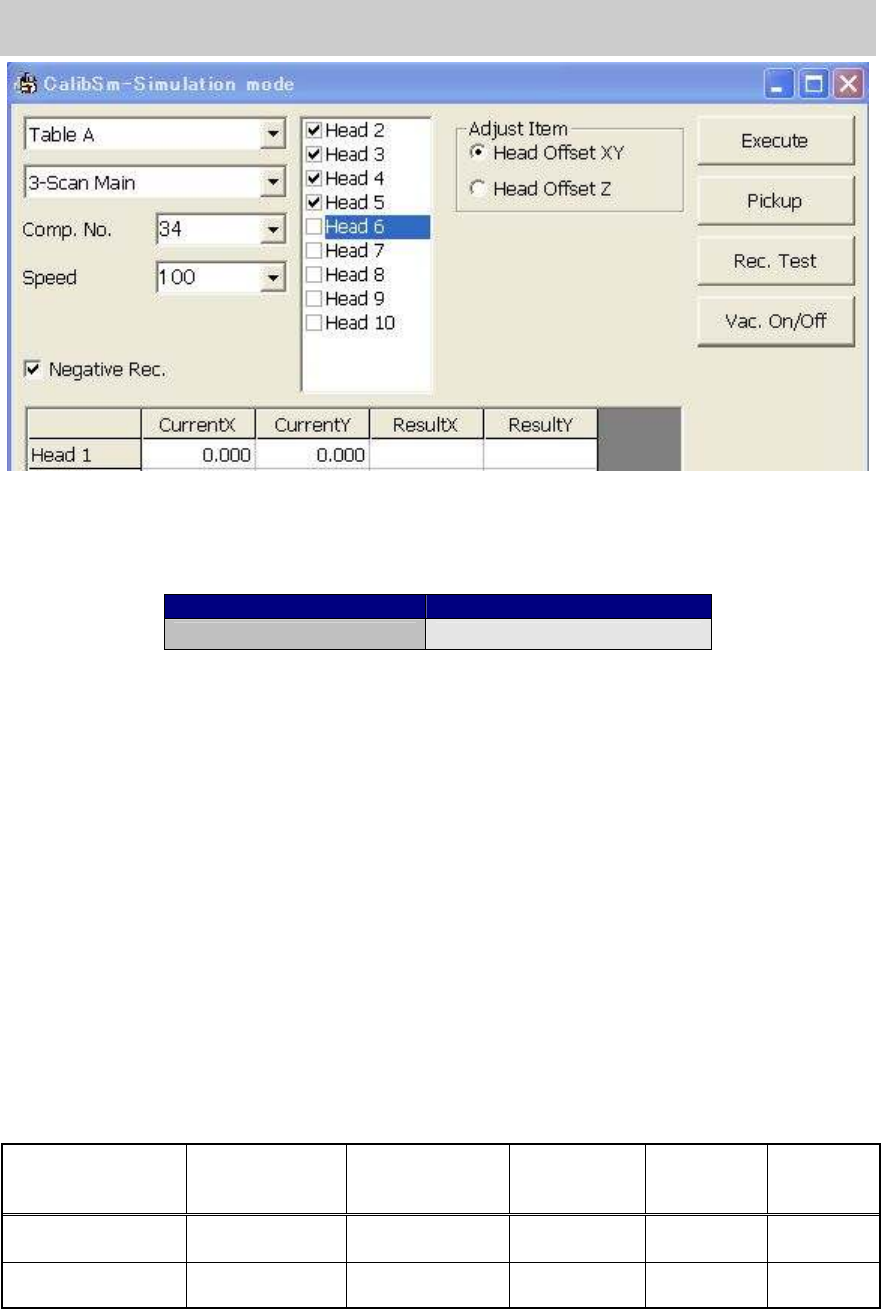
Figure 79
Make the nozzle vacuum the Glass QFP and click on the [Execute] button to start adjustment and
display the compensation values in the “Result X, Y” field. If the values exceed the specified value,
they are indicated in the red letters.
Items to be adjusted Specified value
Head Offset XY Designed value +- 0.06mm
Table 27
* If the head offset does not meet the specified value, it affects the vacuuming and mounting
accuracy. The possible causes are distortion of the shaft, the improper installation of the nozzle,
and so on. Please take the relevant measures.
8.5. How to adjust “Head Offset Z”
The “Vacuum level” needs to be adjusted before performing adjustment for “Head Offset Z”.
Click on the [Head Offset] button on the main screen of the CalibSm and select “Head Offset Z”
from the “Adjust Item” on the “Head Offset” screen.
Perform measurement on the top surface of the aluminum frame of the glass board.
- Nozzle to be used: Type 302A (313A)… (For Chip components)
8.6. Scale adjustment of the multi camera (Option)
Click on the [Multi Camera] button on the main screen of the CalibSm.
[For reference]
Camera No. Camera Type
Mounting
position
Maximum
angle of view
XY (mm)
Maximum
angle of view
Z (mm)
Mounting
angle
Digital camera 5 Digital Multi C
Front/
Either front or rear
24 7 0 degree
Digital camera 6 Digital Multi C Rear 24 7 180 degrees
Table 28
* When the machine is equipped with two multi cameras, the camera mounted on the front side is
Digital camera 5, and the one mounted on the rear side is Digital camera 6.
Service Engineer
Service Information
SI0804004E-000 = YS12, YG12: Procedure for adjustment after installation of the machine
57/60
When the machine is equipped with only one multi camera, whichever side the camera is mounted,
it is Digital camera 5.
Make the nozzle vacuum the Glass QFP and perform adjustment.
- Nozzle to be used: Type 304A (315A) nozzle (For QFP)
- Component to be used: Glass QFP 68pin (KW8-M880A-10* GLASS QFP 68P)
- Part No.:No.11 QFP68_P0.65 (Board data: MCH_SETUP)
Items to be adjusted Specified value
Angle 0.000 +- 0.100
Scale X 24.000 +- 0.100
Scale Y 24.000 +- 0.100
Offset 0.000 +- 0.050
Table 29
8.7. Positioning of the Multi Camera
Click on the [Multi Camera] button on the main screen of the CalibSm.
Select “Camera Pos.” from the “Adjust Item” on the “Multi Camera” screen.
- Nozzle to be used: Type 304A (315A) nozzle (For QFP)
- Component to be used: Glass QFP 68pin (KW8-M880A-10* GLASS QFP 68P)
- Part No.: No.11 QFP68_P0.65 (Board data: MCH_SETUP)
8.8. Check the machine reference
Click on the [Axis] button on the main screen of the CalibSm.
Click on the [Originize] button on the “Axis” screen to perform ”Return to origin”.
If the values do not meet the specification, please investigate the cause of the problem and take
relevant measures.
Axis name Specification (%)
XY 50 +- 5
Z 10 +- 5
R 45 +- 2
W 50 +- 5
PU 50 +- 5
SC 62 +- 5
Table 30
If the values do not fall within specification, click on the [Originize] button again in order to check if
the reference values are stable.
Repeatability of the reference: Within +-2%
Service Engineer
Service Information
SI0804004E-000 = YS12, YG12: Procedure for adjustment after installation of the machine
58/60
9. Items to be checked after accuracy adjustment
9.1.Check if the board is transferred properly from the upstream machine to the
downstream machine
1. Output request signal to the upstream machine, and check the signal sent from the
downstream machine on the “I/O” tab on the “Unit” screen,
2. Change the setting of the “Conveyor Spec” to “Line”.
Click on the [Edit] button on the “Sequence” tab on the “Board” screen, and then select “Skip”
from the “Mount item” in order to transfer a board from the upstream machine to the
downstream machine.
9.2.Check the pickup position of the feeder
Click on the [FeederPos] button on the main screen of the CalibSm and check the pickup
position of the feeder.
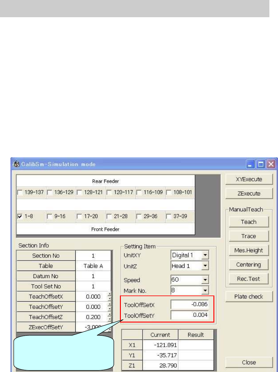
Figure 80
Input the compensation value
(Offset value) of the tool to be
used before adjustment.