YS12调整.pdf - 第3页
Service Engineer Service I nformati on SI080 4004 E-000 = YS12 , YG12: Procedure for adjustmen t after installa tion of the mach ine 3/60 1. Before replacem ent Please mak e sure to check the following for safety before …

Service Engineer
Service Information
SI0804004E-000 = YS12, YG12: Procedure for adjustment after installation of the machine
2/60
7.4. Check the result of the measurement .................................................................................. 51
8. Items to be adjusted relating to the mounting accuracy of the machine ..................................... 54
8.1.How to perform scale adjustment of the fiducial camera ......................................................54
8.2.How to perform scale adjustment of the scan camera .......................................................... 54
8.3. Positioning of the Scan Camera (Main camera)................................................................... 55
8.4. How to adjust “Head Offset XY” ........................................................................................... 55
8.5. How to adjust “Head Offset Z”.............................................................................................. 56
8.6. Scale adjustment of the multi camera (Option) .................................................................... 56
8.7. Positioning of the Multi Camera............................................................................................ 57
8.8. Check the machine reference .............................................................................................. 57
9. Items to be checked after accuracy adjustment..........................................................................58
9.1.Check if the board is transferred properly from the upstream machine to the downstream
machine ....................................................................................................................................... 58
9.2.Check the pickup position of the feeder ................................................................................ 58
9.3. Check the operation of the blow station ............................................................................... 59
9.4. Check the “PCB origin”.........................................................................................................59
9.5. Check the operation of the “Nozzle change” function (Option)............................................. 59
9.6. Check the operation of the feeder exchange carriage (Option) ...........................................59
10.Change the settings back to the customer’s setting and confirm the setting ............................. 60
11.Data backup ............................................................................................................................... 60
Service Engineer
Service Information
SI0804004E-000 = YS12, YG12: Procedure for adjustment after installation of the machine
3/60
1. Before replacement
Please make sure to check the following for safety before performing the adjustment.
1) All the fixing brackets are removed from the axes, and no removed brackets are left in the
machine.
2) The levels are not left in the machine.
3) The machine signal tower and the harness of the signal tower are properly secured.
4) There are no tools or foreign objects left in the machine, and also no interference exists
between the axes, head and other parts.
5) The primary power source of the machine is properly connected.
6) The primary air is properly supplied, there is no air leak and the air pressure is normal.
2. Required tools for adjustment
2.1. Tools for “Brightness adjustment”
<For the fiducial cameras and the multi cameras>
Part No. Part Name Size Feature
KM1-M8806-0XX
LIGHT ADJUSTER
35mm
square
Dark and light gray + white
KM1-M8806-1XX
LIGHT ADJUSTER 1
35mm
square
Dark and light gray + white,
With a Φ3 hole
KGT-M8806-0XX
LIGHT ADJUSTER S
17mm
square
Light gray and white
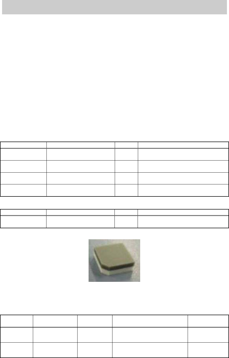
KHW-M8806-XXX
LIGHT ADJ.*(1,S, 3,4)
ASSY
35mm
square
Dark and light gray + white,
With one chamfered corner
<For the scan cameras>
Part No. Part Name Size Feature
KHW-M8806-D0X
LIGHT ADJ.4 ASSY
11mm
square
Light gray and white
Table 1
Figure 1
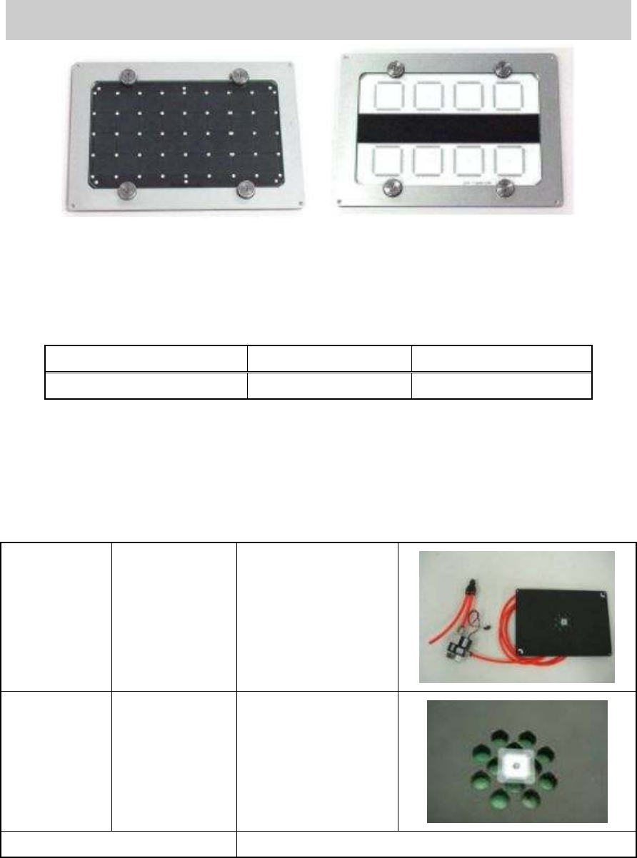
2.2. Glass board for adjustment
(If the ACP board cannot be prepared, use the AMF board)
Board type
Part Number Part Name Board data
Double-faced
tape to be used
ACP
Glass board
KM0-M8810-400
GLASS PCB
ASSY.4
ACP_1005_10HEAD_FL.ygx 20mm width
AMF
Glass board
KM0-M8810-100
GLASS PCB
ASSY.1
ACP_1005_10HEAD_OLD.ygx
35mm width
Table 2
Service Engineer
Service Information
SI0804004E-000 = YS12, YG12: Procedure for adjustment after installation of the machine
4/60
< ACP Glass board> < AMF Glass board>
Figure 2
2.3. Component for mounting adjustment
Component Part No. Part Name
1005 Ceramic chip (reel) KGA-M880C-10* REEL CERAMIC 1005
Table 3
2.4. Tools used for multi camera adjustment (Option)
Adjustment using the QFP68 pin and FAMF station needs to be performed in addition to the ACP
adjustment using the 1005 chip components.
FAMF Station
(240*170)
KGA-M88F0-A0X
FAMF STATION
ASSY.
Glass QFP68
Pin
KW8-M880A-10X
GLASS QFP 68P
Board data FAMF_QFP68_ST_H48.ygx
Table 4