YS12调整.pdf - 第28页
Service Engineer Service I nformati on SI080 4004 E-000 = YS12 , YG12: Procedure for adjustmen t after installa tion of the mach ine 28/60 Note: <When the reference camera is replaced> “Digital 2” indicates sub cam…
Service Engineer
Service Information
SI0804004E-000 = YS12, YG12: Procedure for adjustment after installation of the machine
27/60
4.7. How to adjust the “Fiducial camera relative position”(Option)
YS12 and YG12 models are equipped with two fiducial cameras at the user’s option.
By using the sub fiducial camera (mounted on the left side of the head), the pick up position of the
components that cannot be recognized with the reference camera (mounted on the right side of
the head) can be recognized and the coordinate can be precisely obtained.
The relative position of the reference camera and the sub camera is accurately adjusted by the
utility.
Normally, the position of the sub camera is adjusted based on the position of the reference camera.
The position coordinate of the reference camera is adjusted by the ACP adjustment.
[Tools required for adjustment]
Please use either of the following boards.
KM0-M8810-400 GLASS PCB ASSY.4 ACP class board
KM0-M8810-100 GLASS PCB ASSY.1 AMF glass board
Table 18
4.7.1. Adjustment procedure
1. Select the “Fiducial camera relative position”.
Click on the [Fiducial Camera relative Pos] button on the main menu of CalibSm.
Figure 36
2.
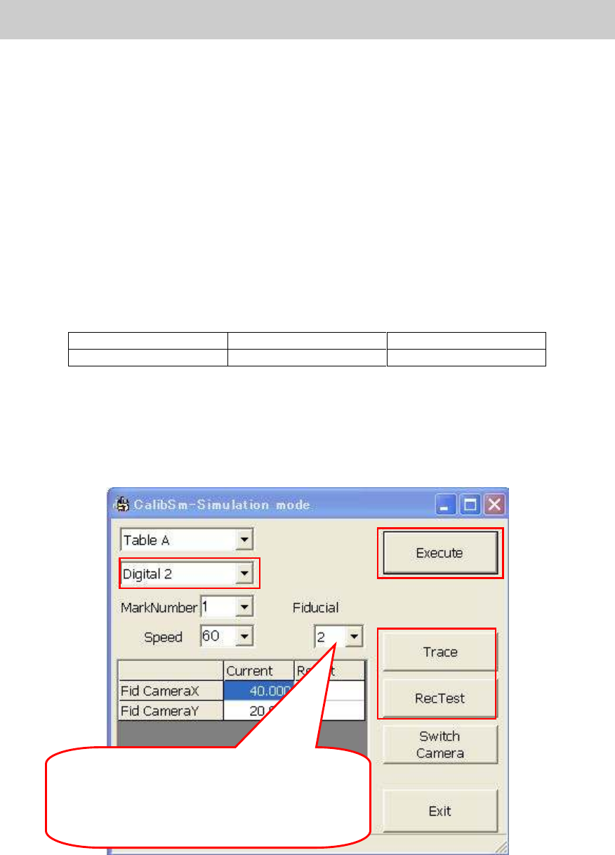
Check the camera number.
Check if “Digital 2” is selected from the dropdown list of the camera number.
Set which fiducial mark of the board is to be
used. Normally, it is set automatically depends
on the conveyor direction.
- From right to left: 2
- From left to right: 1
2
5
3
4
1
Service Engineer
Service Information
SI0804004E-000 = YS12, YG12: Procedure for adjustment after installation of the machine
28/60
Note:
<When the reference camera is replaced>
“Digital 2” indicates sub camera. When the reference camera is replaced and the coordinate of the
reference camera is adjusted, change the camera number to “Digital 1” and perform adjustment
based on the coordinate of the sub camera.
3. Trace the mark.
Set the glass board on the conveyor and click on the [Trace] button.
The head moves to the position where the mark (Φ0.5 mark on the board) can be
recognized.
4. Mark recognition test
Move the specified camera to the center of the mark to perform mark recognition test. If the
recognition error occurs, investigate the cause of the problem on the [Mark Adj] screen and
take proper measures, then perform recognition test again.
Figure 37
5. Click on the [Execute] button.
Click on the [Execute] button to recognize the same mark with the two cameras.
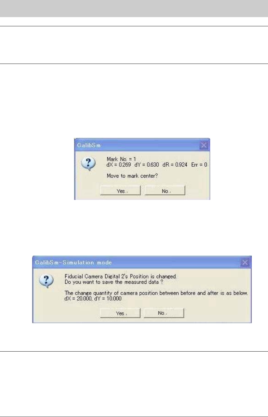
6. Save the measured data.
When the adjustment is completed, the dialog box appears asking you to save the data.
Figure 38
Check if the camera number is correct and the variation is normal, and then save the data.
Note:
- The [Switch camera] button is not normally used in this utility. The coordinate of the selected
camera is adjusted based on the coordinate of the other (adjusted) camera. The coordinate
adjustment of the two cameras cannot be performed at the same time with this utility.
- If the positional relation of the two cameras is not changed mechanically (including lens, CCD
and so on), the adjustment does not need to be performed.
- When the coordinate of the reference camera is changed in the ACP adjustment, the
coordinate of the sub camera is changed as well.

Service Engineer
Service Information
SI0804004E-000 = YS12, YG12: Procedure for adjustment after installation of the machine
29/60
5. How to check the mounting accuracy (with ACP
1
)
5.1. Preparation for the ACP adjustment
Scan camera is used as a reference camera when performing adjustment of the mounting
accuracy of the YS12 and YG12 models.
Mounting accuracy adjustment is performed by ACP using the ceramic chip.
The nozzle 301A (312A) and the 1005 chip component are normally used for performing the
adjustment.
If the machine is equipped with multi cameras (option), after performing the ACP adjustment with
multi camera using the 1005 chip adjustment, perform FAMF adjustment by mounting the Glass
QFP 68 pin with the 304A (315A) nozzle.
Please make sure to perform the following adjustments (work) before performing the ACP
adjustment (mounting accuracy adjustment) when installing or relocating a machine.
System data back up
Make a backup copy of the system data before performing adjustment after installation of the machine,
or maintenance.
Adjustment of the Y-axis dual drive offset
Correct the deviation between the Y1-axis motor and the Y2-axis motor caused by the relocation of the
machine. The adjustment does not need to be performed when the machine is not relocated or the
motor is not replaced.
Adjustment of the “Orthogonalization level”
Correct the deviation in orthogonality of the axes after relocating a machine.
The adjustment does not need to be performed when the machine is not relocated or the Coord Macs
adjustment is performed.
Adjustment of the “Brightness” (Illumination intensity of lighting) for each camera
Basically the adjustment needs to be performed when the installation environment of the machine is
changed. However if the adjustment is performed during maintenance, it affects the customer’s existing
production data. Please make sure to gain the customer’s approval before performing the adjustment.
Adjustment of the “Fiducial Camera relative position” (Option)
Correct the deviation of the relative position between the reference camera and the sub camera caused
by the relocation of the machine.
[Reference]
Digital camera numbers
Camera No. Type Mounting point
Maximum angle
of view
XY (mm)
Maximum
angle of view
Z (mm)
Mounting
angle
Digital camera 1 Moving camera B
Right side of the head
5 0 90 degrees
Digital camera 2 Moving camera B
Left side of the head
5 0 270 degrees
Digital camera 3 Scan, Main 8 7 0 degree
Digital camera 4 Scan Side view
Integrated
4 2 90 degrees
Digital camera 5 Digital Multi C
* Front /
One multi camera
24 7 0 degree
Digital camera 6 Digital Multi C Rear 24 7 180 degree
Table 19
* When the machine is equipped with two multi cameras:
- Front “Digital 5 / - Rear: Digital 6
When the machine is equipped with only one camera:
Wherever the camera is mounted (Front or Rear), the camera is “Digital 5”.
1
ACP(Accuracy Calibration Program) is an adjustment function for the mounting accuracy used in Calib Sm, which is in
the [Utilities] for YAMAHA surface mounter; YG and YS series.