YS12调整.pdf - 第46页
Service Engineer Service I nformati on SI080 4004 E-000 = YS12 , YG12: Procedure for adjustmen t after installa tion of the mach ine 46/60 5. Check the operation of the ejec tor on the I/O screen Open the “Unit” screen a…
Service Engineer
Service Information
SI0804004E-000 = YS12, YG12: Procedure for adjustment after installation of the machine
45/60
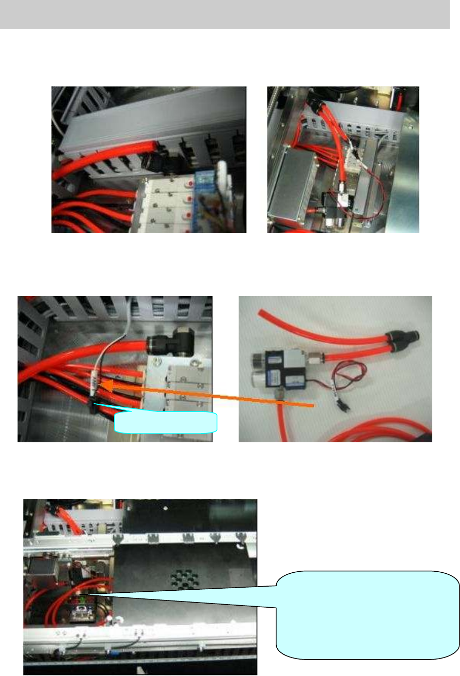
2. Air piping
Disconnect the hose of the air valve at the far side on the left side of the pushup plate, and
connect the ejector to where the hose of the air valve was connected.
Figure 60
3. Connect the ejector
Take out the harness “AMF1” used for generating the ejector from the duct at the far left at
the pushup plate, and connect the connector of the station to the AMF 1 connector.
Figure 61
4. Clamp the station board
Connect the Φ 6mm air hose of the ejector to the air joint on the back of the station.
Change the conveyor width to 170.0mm, set the station and secure it by board clamp.
Figure 62
AMF1Connector
[Warning]
Please connect the air hose to
lower than the conveyor height so
that it does not interfere with the
head.
Service Engineer
Service Information
SI0804004E-000 = YS12, YG12: Procedure for adjustment after installation of the machine
46/60
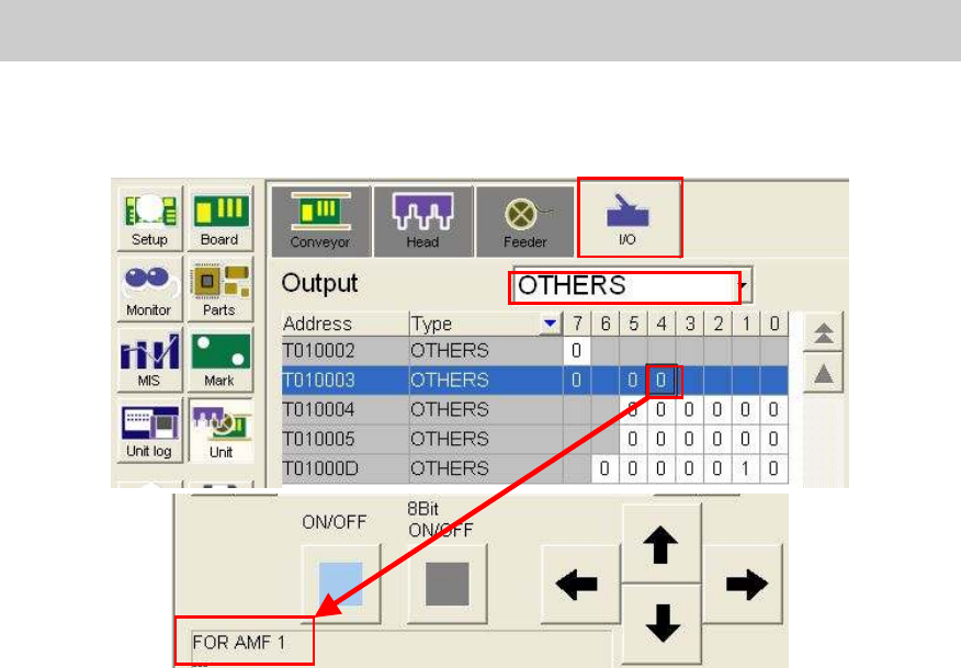
5. Check the operation of the ejector on the I/O screen
Open the “Unit” screen and select “Others” from the dropdown list on the “Output” side on the
“I/O” tab.
Figure 63
When the ejector is connected to “AMF 1” connector, please select [T0100034].
6. Check the operation of the ejector.
Check the operation of the ejector by selecting “T0100034” and clicking on the [ON/OFF]
button.
7.3.3. Read the FAMF board data
Read the board data for FAMF adjustment.
Board data: FAMF_QFP68_ST_H48.ygx
The FAMF adjustment for the multi camera is performed by mounting the Glass QFP68 pin with
the 304A (315A) nozzle.
The nozzle does not come with the machine as standard equipment; please prepare it before
adjustment if the customer does not have it.
The heads to be used are “Head 4” and “Head 8”.
7.3.4. Recognition of the mark and the component
In FAMF adjustment, Glass QFP68 pin is picked up from the station, recognized and mounted on
the station. Then after the camera recognizes the mounting state of the component, the
component is picked up again for recognition repeatedly.
Please make sure to perform recognition check in advance so that no error occurs during the
sequence of the operation.
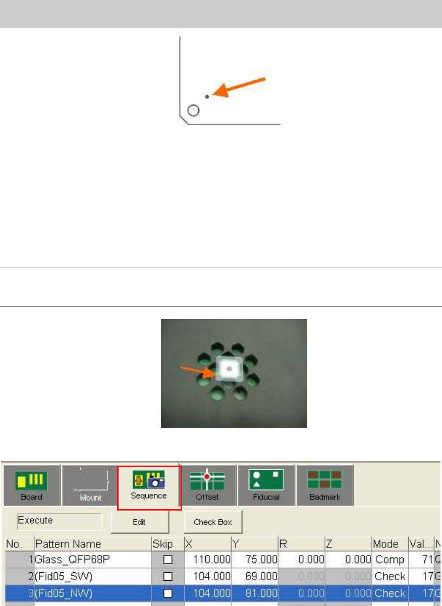
1. Recognize the fiducial marks on the FAMF station.
TheΦ1.0mm holes at the lower left and at the upper right on the station board are recognized
as the marks.
Mark No.: No.2 Hall_1.0_Circle
Move the camera to the fiducial coordinate and perform recognition check on the “Mark
adjust” screen.
Service Engineer
Service Information
SI0804004E-000 = YS12, YG12: Procedure for adjustment after installation of the machine
47/60
Figure 64
2. Recognition check of the Glass QFP68 pin.
Perform recognition of the Glass QFP68 pin with the Head 4 or the Head 8.
Part No.: NO.71 QFP68_P0.65_t=1.0
Please perform recognition check on the “Parts adjust” screen.
3. Recognition of the mark on the Glass QFP.
Place the Glass QFP68 pin in the center of the FAMF station board, and recognize one of the
marks at the four corners of the Glass QFP.
Note:
- Please clean the surface of the glass QFP.
- Please set the glass QFP with the printed side facing down..
Figure 65
[How to perform “Mark trace” (Moving the camera to the mark)]
Figure 66
Select “Sequence” tab on the “Board” screen and select “Check” from the “Mode” column.
Click on the [Teach] button to display the “Sequence” screen.
Click on the [Trace] button to move the camera to the mark on the board.
Mark No.: NO.17 GlassQFP_0.5_Circle
Please perform recognition check on the “Mark adjust” screen.