YS12调整.pdf - 第26页
Service Engineer Service I nformati on SI080 4004 E-000 = YS12 , YG12: Procedure for adjustmen t after installa tion of the mach ine 26/60 If the data is corrected, please perf orm meas urement again after s aving the Co…
Service Engineer
Service Information
SI0804004E-000 = YS12, YG12: Procedure for adjustment after installation of the machine
25/60
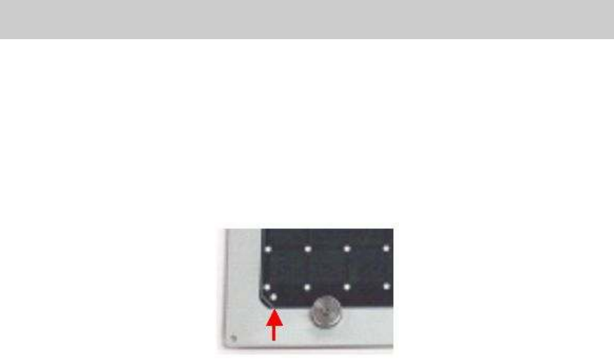
4. Check the reference coordinate of the mark.
Click on the [Trace] button to move the camera to the mark (Φ0.5mm)at the left bottom of the
board.
Then click on the [Teach] button to display the “Teaching” screen. Check if the mark is in the
recognition range, then click on the [OK] button.
Centering is performed and the coordinate of the mark center is obtained automatically.
5. Click on the [Execute] button.
The four marks at the corners of the board are recognized based on the reference coordinate.
After the recognition is completed, the screen to indicate the variation of the perpendicularity
of the axes is displayed.
Figure 33
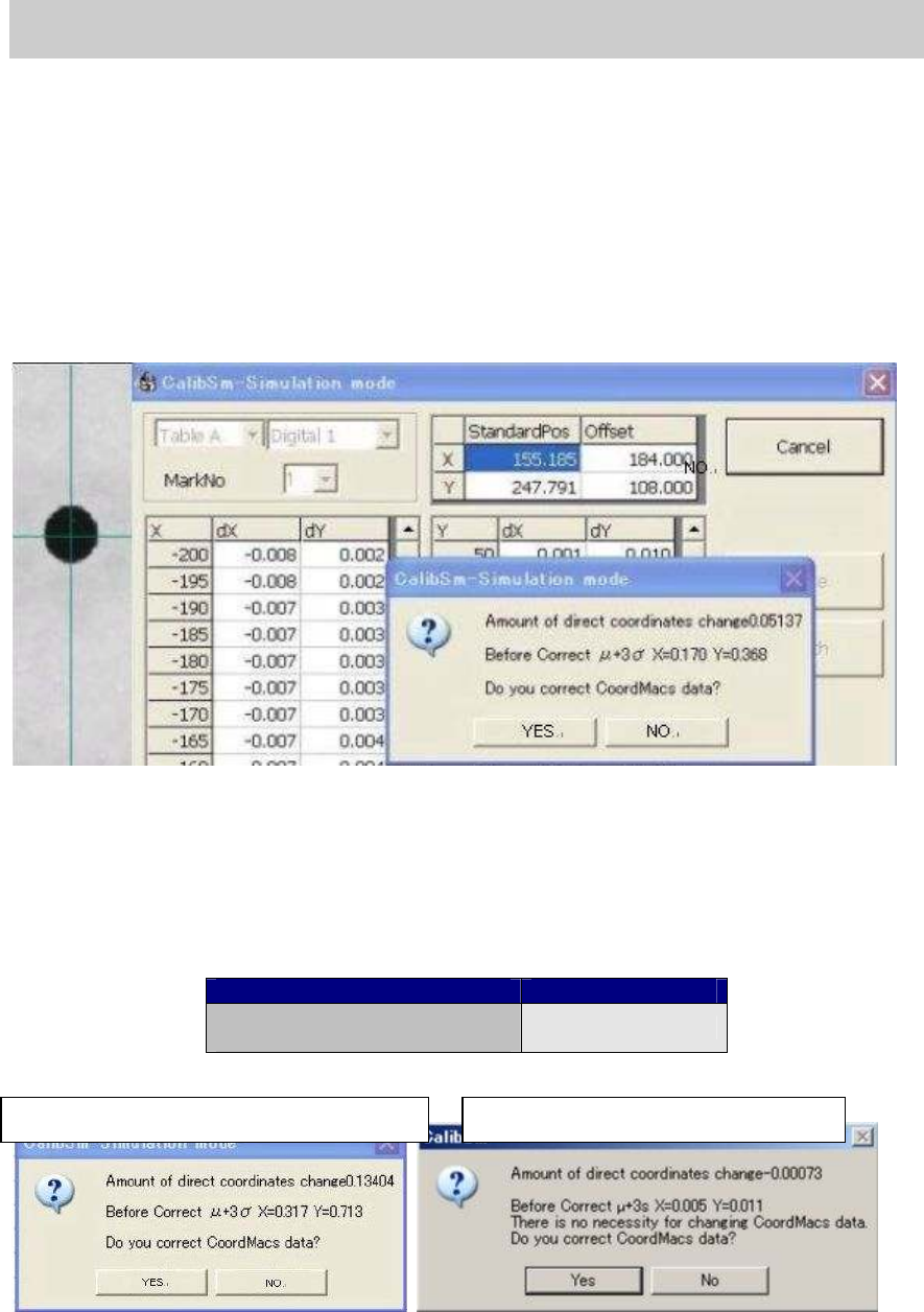
6. Check the variation of the perpendicularity.
When the measurement is completed, the dialog box appears asking you if the CoordMacs
data needs to be corrected. If the data needs to be corrected, click on the [Yes] button to save
the data. After the data is saved, the measurement is performed again.
If the variation of the perpendicularity falls within the specification (0.0015deg.), click on the
[No] button.
Item Specification
The specification for the
variation of the perpendicularity
0.0015 deg
Table 17
Figure 34
When the value does not meet the spec.
When the value meets the spec.
Service Engineer
Service Information
SI0804004E-000 = YS12, YG12: Procedure for adjustment after installation of the machine
26/60
If the data is corrected, please perform measurement again after saving the Coord Macs data.
Check if the variation of the perpendicularity falls within the specification, save the data and fill in
the value on the check sheet.
[If the mark recognition cannot be performed successfully]
Check if the board is clamped properly and the mark is not contaminated.
Check if the mark can be recognized by selecting the mark information “NO.1
Glass_0.5_Circle “ and performing recognition check on the “Mark Adjust” screen.
Figure 35
Service Engineer
Service Information
SI0804004E-000 = YS12, YG12: Procedure for adjustment after installation of the machine
27/60
4.7. How to adjust the “Fiducial camera relative position”(Option)
YS12 and YG12 models are equipped with two fiducial cameras at the user’s option.
By using the sub fiducial camera (mounted on the left side of the head), the pick up position of the
components that cannot be recognized with the reference camera (mounted on the right side of
the head) can be recognized and the coordinate can be precisely obtained.
The relative position of the reference camera and the sub camera is accurately adjusted by the
utility.
Normally, the position of the sub camera is adjusted based on the position of the reference camera.
The position coordinate of the reference camera is adjusted by the ACP adjustment.
[Tools required for adjustment]
Please use either of the following boards.
KM0-M8810-400 GLASS PCB ASSY.4 ACP class board
KM0-M8810-100 GLASS PCB ASSY.1 AMF glass board
Table 18
4.7.1. Adjustment procedure
1. Select the “Fiducial camera relative position”.
Click on the [Fiducial Camera relative Pos] button on the main menu of CalibSm.
Figure 36
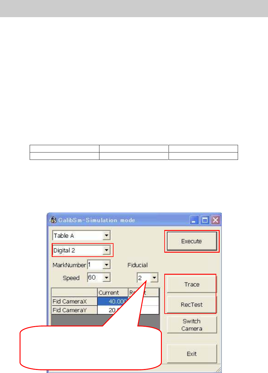
2.
Check the camera number.
Check if “Digital 2” is selected from the dropdown list of the camera number.
Set which fiducial mark of the board is to be
used. Normally, it is set automatically depends
on the conveyor direction.
- From right to left: 2
- From left to right: 1
2
5
3
4
1