YS12调整.pdf - 第44页
Service Engineer Service I nformati on SI080 4004 E-000 = YS12 , YG12: Procedure for adjustmen t after installa tion of the mach ine 44/60 7.3. F A MF adjustment of the mult i camera (G lass QFP 68 pin) After com pleting…
Service Engineer
Service Information
SI0804004E-000 = YS12, YG12: Procedure for adjustment after installation of the machine
43/60
7. Accuracy adjustment of the multi camera (Option)
If the machine is equipped with the multi camera, please perform accuracy adjustment of the multi
camera (sub camera) after the accuracy adjustment of the scan camera (main camera) is
completed.
7.1. The flow of the accuracy check and adjustment of the multi camera
Note:
When performing adjustment of the basic data (“Scale”, “Camera pos.” and “Head Offset”)
of the scan camera (main camera) in ACP adjustment, please perform “Scale” adjustment , and
“Camera pos.” adjustment of the multi camera before performing ACP adjustment of the multi
camera.
1. Perform ACP accuracy check and adjustment with 301A (313A) nozzle (Ceramic 1005).
2. Perform FAMF accuracy check and
adjustment with 304A (315A) nozzle (Glass QFP68 pin).
7.2. ACP accuracy check of the multi camera (1005 ceramic chip)
The tools required for adjustment, the board name and the adjustment procedure are the same as
that of the ACP adjustment of scan camera. Please refer to “5. How to check the mounting
accuracy (with ACP)” for details.
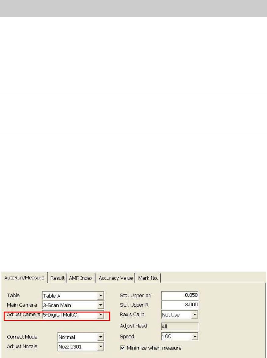
1. How to change the settings
Click on the [ACP] button on the main menu of CalibSm. Change the camera number of the
“Adjust Camera” item to “5-digital MultiC” on the “AutoRun/Measure” tab.
If the machine is equipped with two multi cameras: Front Digital 5 / Rear Digital 6
If the machine is equipped with only one multi camera: Wherever (Front or rear) the camera is
mounted, it is Digital 5.
Figure 58
2. Start ACP adjustment
Check the settings and click on the [All] button to start ACP adjustment.
3. Perform feedback for the ACP adjustment.
The workflow after completing the ACP adjustment of the multi camera is basically the same
as that of the scan camera (main). Please refer to “5.2.2. Mounting and measurement
performed by ACP” for the adjustment procedure.
Service Engineer
Service Information
SI0804004E-000 = YS12, YG12: Procedure for adjustment after installation of the machine
44/60
7.3. FAMF adjustment of the multi camera (Glass QFP 68 pin)
After completing the ACP adjustment of the multi camera with the 1005 ceramic chip, please
perform mounting adjustment by picking up the Glass QFP68 pin by 304A (315A) nozzle on the
FAMF station.
7.3.1. Tools required for adjustment
1. FAMF station
Part No. Part Name
FAMF Station(240*170)
KGA-M88F0-A0X FAMF STATION ASSY
Board data: FAMF_QFP68_ST_H48.ygx
2. The mounted component for adjustment
Part No. Part Name
Glass QFP68 pin KW8-M880A-10X GLASS QFP 68P
3. Nozzle for adjustment
Part No. Part Name
Type 304A(315A) nozzle
(For QFP)
KHY-M7750-A0X NOZZLE 304A/315A AS
Table 23
7.3.2. Initial setup for the FAMF station
Perform air piping and the wiring in order to use the FAMF station.
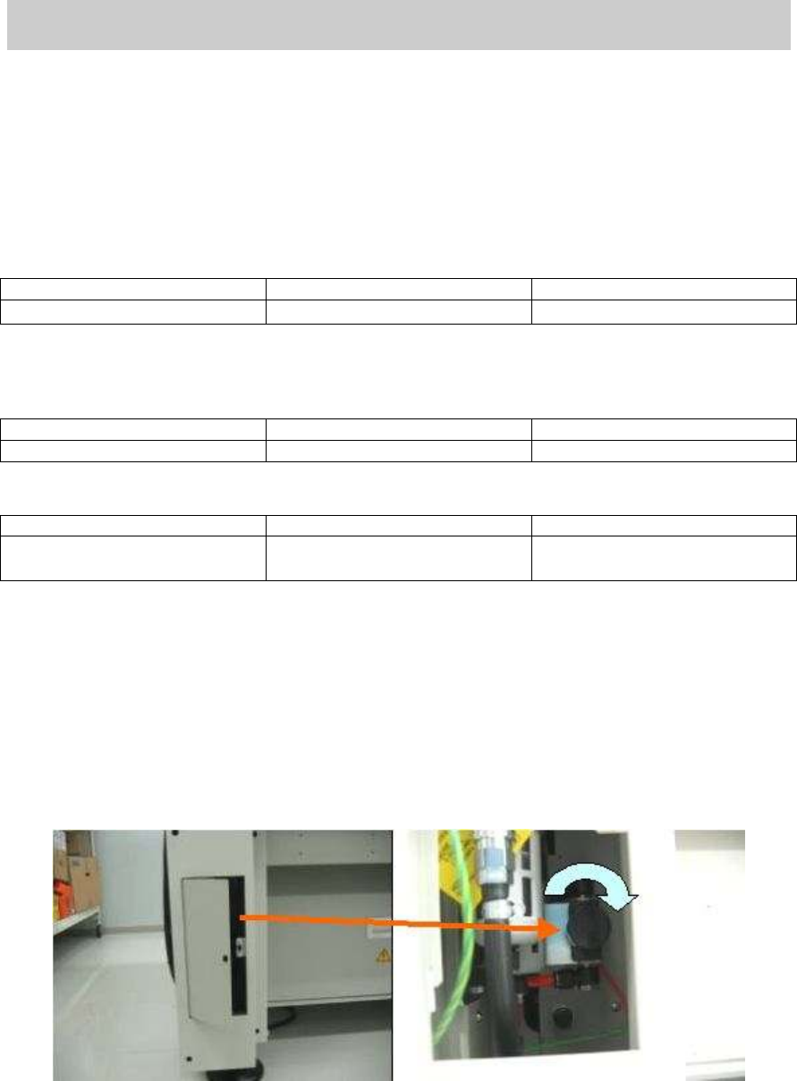
1. Stop the main air supply.
Turn the “Air pressure supply / shutoff” switch inside the cover at the left bottom of the
machine to the right in order to shut off the air supply.
Figure 59
Service Engineer
Service Information
SI0804004E-000 = YS12, YG12: Procedure for adjustment after installation of the machine
45/60
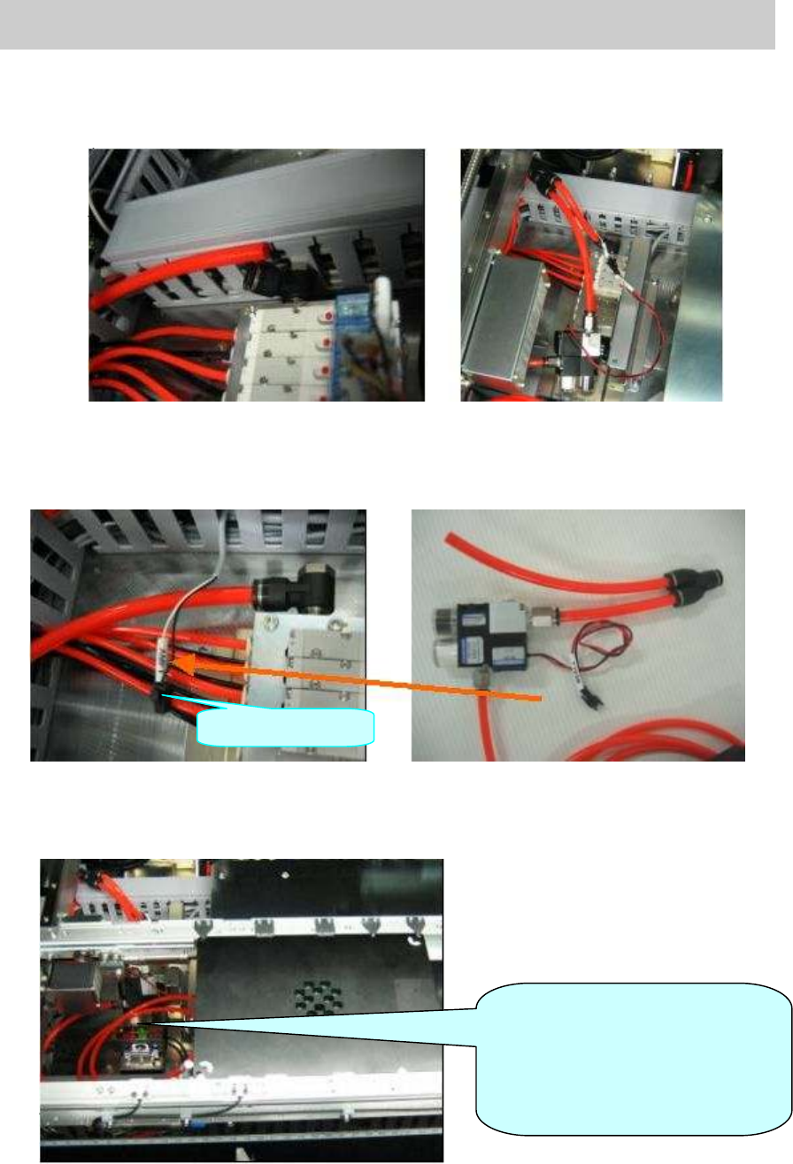
2. Air piping
Disconnect the hose of the air valve at the far side on the left side of the pushup plate, and
connect the ejector to where the hose of the air valve was connected.
Figure 60
3. Connect the ejector
Take out the harness “AMF1” used for generating the ejector from the duct at the far left at
the pushup plate, and connect the connector of the station to the AMF 1 connector.
Figure 61
4. Clamp the station board
Connect the Φ 6mm air hose of the ejector to the air joint on the back of the station.
Change the conveyor width to 170.0mm, set the station and secure it by board clamp.
Figure 62
AMF1Connector
[Warning]
Please connect the air hose to
lower than the conveyor height so
that it does not interfere with the
head.