YS12调整.pdf - 第24页
Service Engineer Service I nformati on SI080 4004 E-000 = YS12 , YG12: Procedure for adjustmen t after installa tion of the mach ine 24/60 4.6. Ort hogonalization level W hen the machine is adjusted at the fac tory befor…
Service Engineer
Service Information
SI0804004E-000 = YS12, YG12: Procedure for adjustment after installation of the machine
23/60
Figure 29
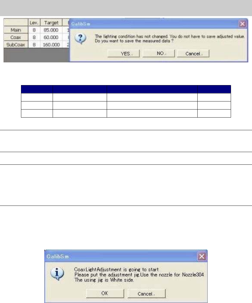
[Specification]
Color of the tool Tolerance of the measured value
Bit value
Main Light gray 85+-2 128 - 532
Coax White 60+-2 128 - 532
Sub Coax
White 160+-2 128 - 532
Table 15
Note:
If the Bit value does not fall within the specification, please check if the lens of the camera is clean,
if the lighting condition is good, or if the connector is connected properly.
Note:
As the maximum value of the Bit value is the warning value for the upper limit, the adjustment can
be performed even when the value exceeds the specification.
If the Bit value exceeds 532 (the seven eighth of the maximum value), it may attribute to the
deterioration of the lighting device. It is recommended to replace the lighting.
(The maximum value of the Bit value: 608)
8. Adjust the brightness of “Coax” and “Sub Coax”.
After completing adjustment of the main lighting, perform adjustment of “Coax” and “sub
coax” lighting according to the message in the dialog box.
Reverse the tool for brightness adjustment so that the white side faces down.
Figure 30
9. Save the adjusted data.
Perform adjustment, check the result, save the data and fill in the check sheet for both “coax”
and “Sub coax” lightings.
10. Remove the tool for brightness adjustment.
When the adjustment is completed, press the [Emergency stop] button and remove the tool.
And then click on the [Vac. ON/OFF] button to disable the nozzle to vacuum the tool.
If the 304A (315A) nozzle is mounted by hand for adjustment, change the nozzle to the original
one.
Service Engineer
Service Information
SI0804004E-000 = YS12, YG12: Procedure for adjustment after installation of the machine
24/60
4.6. Orthogonalization level
When the machine is adjusted at the factory before shipment, the distortion of the coordinates is
corrected with ”Coord Macs“ function. ”Orthogonalization level” function corrects the perpendicular
deviation of the axes caused by the relocation of the machine.
Please make sure to perform ”Orthogonalization level” adjustment when the machine is relocated.
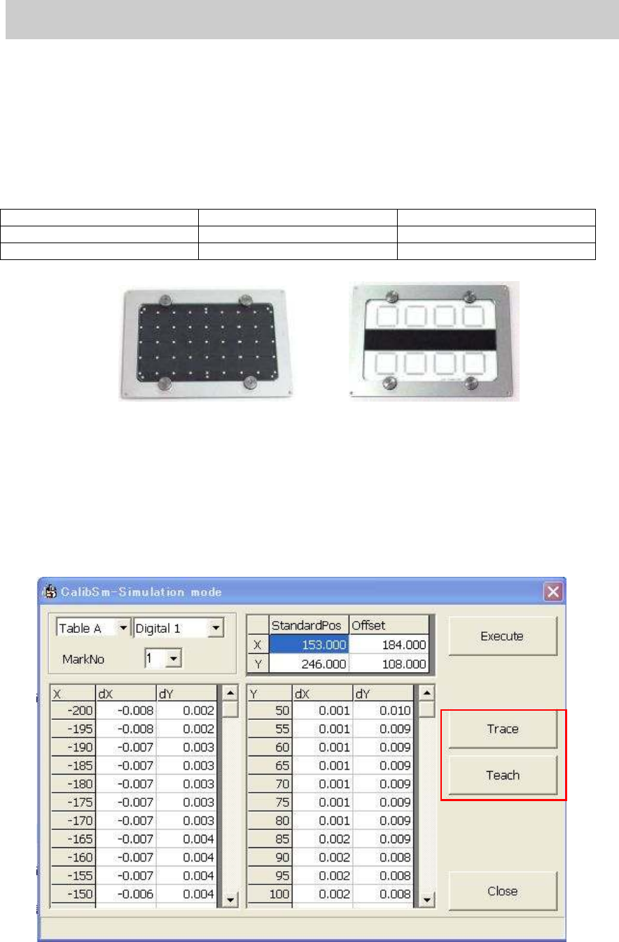
[Required tool]
Glass board for adjustment. (Please prepare either of the following.)
Part No. Part Name
1) ACP Glass board KM0-M8810-400 GLASS PCB ASSY.4
2) AMF Glass board KM0-M8810-100 GLASS PCB ASSY.1
Table 16
Figure 31
1. Read the board data (MCH_SETUP)
Read the board data (MCH_SETUP) before starting adjustment.
2. Set the glass board.
Change the conveyor width to the same as the board width (170.00mm) on the “Unit” screen,
then set the glass board to the mounting position and clamp the board.
3. Click on the [Orthogonalization level] button on the main menu of CalibSm.
Click on the [Orthogonalization level] button to display the following screen.
Figure 32
1)
2)
Service Engineer
Service Information
SI0804004E-000 = YS12, YG12: Procedure for adjustment after installation of the machine
25/60
4. Check the reference coordinate of the mark.
Click on the [Trace] button to move the camera to the mark (Φ0.5mm)at the left bottom of the
board.
Then click on the [Teach] button to display the “Teaching” screen. Check if the mark is in the
recognition range, then click on the [OK] button.
Centering is performed and the coordinate of the mark center is obtained automatically.
5. Click on the [Execute] button.
The four marks at the corners of the board are recognized based on the reference coordinate.
After the recognition is completed, the screen to indicate the variation of the perpendicularity
of the axes is displayed.
Figure 33
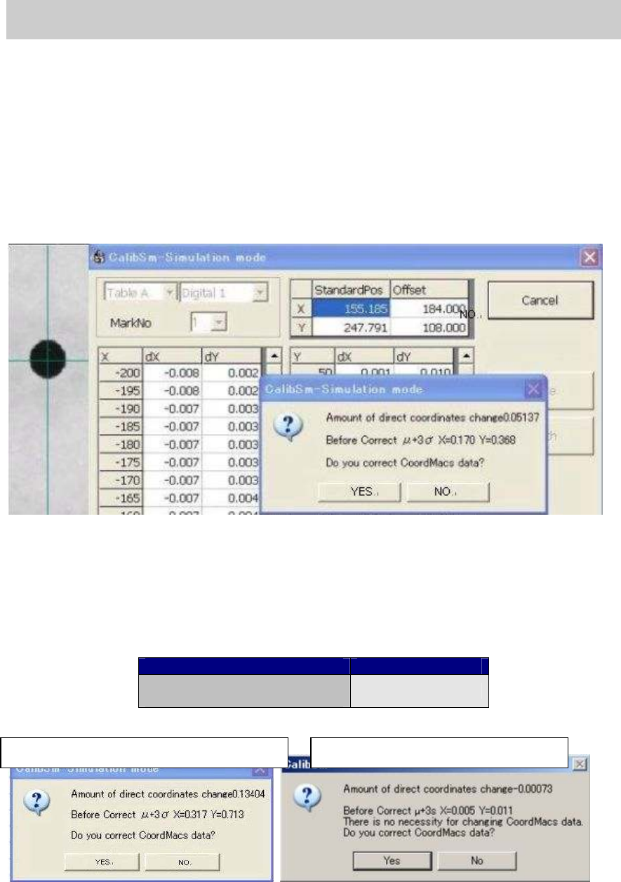
6. Check the variation of the perpendicularity.
When the measurement is completed, the dialog box appears asking you if the CoordMacs
data needs to be corrected. If the data needs to be corrected, click on the [Yes] button to save
the data. After the data is saved, the measurement is performed again.
If the variation of the perpendicularity falls within the specification (0.0015deg.), click on the
[No] button.
Item Specification
The specification for the
variation of the perpendicularity
0.0015 deg
Table 17
Figure 34
When the value does not meet the spec.
When the value meets the spec.