YS12调整.pdf - 第32页
Service Engineer Service I nformati on SI080 4004 E-000 = YS12 , YG12: Procedure for adjustmen t after installa tion of the mach ine 32/60 5.1.3. How to display the FA M F screen Though it is not directly related to the …
Service Engineer
Service Information
SI0804004E-000 = YS12, YG12: Procedure for adjustment after installation of the machine
31/60
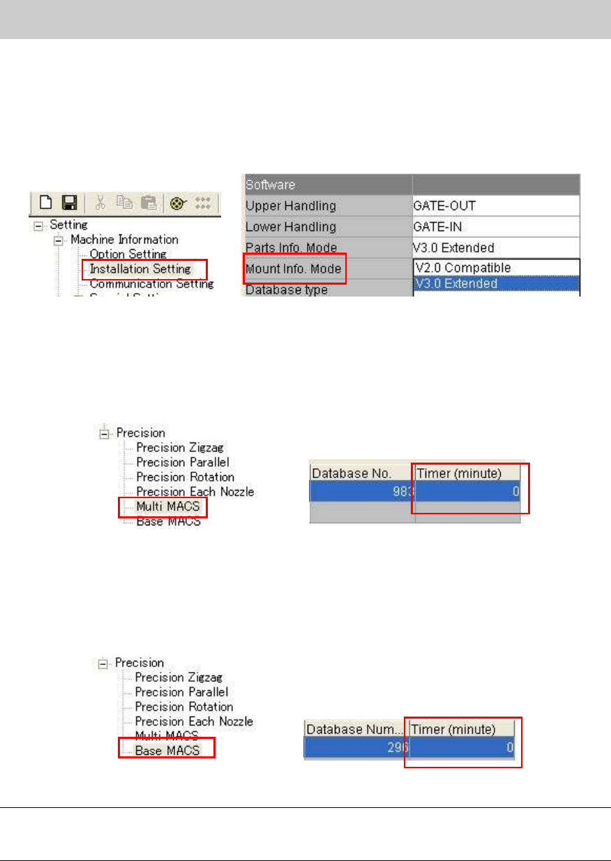
“Mount Info. Mode”
* This mode needs to be set when the machine is equipped with the multi camera.
How to change the setting:
Select “V3.0 Extended” from the dropdown list of the “Parts Info. Mode” in the “Machine
setting”.
Figure 41
“Multi MACS”
As accuracy of repeatability is checked during APC adjustment, the interval time to recognize the
multi MACS needs to be set to 0 in order to recognized Multi MACS each time.
Check if the “Timer (minute)” is set to “0” on the “Multi MACS” screen in the “Precision”.
Figure 42
“Base MACS”
In order to prevent the variation in accuracy from occurring depends on the time for mounting, set
the interval time to “0” so that Multi MACS is recognized each time.
Check if the “Timer (minute)” is set to “0” on the “Base MACS” screen in the “Precision”.
Figure 43
Note:
Please read the board data again in order to reflect the changes when changing the machine
setting.
Service Engineer
Service Information
SI0804004E-000 = YS12, YG12: Procedure for adjustment after installation of the machine
32/60
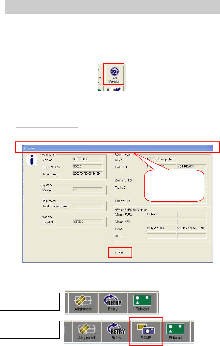
5.1.3. How to display the FAMF screen
Though it is not directly related to the ACP adjustment, if “Station” is selected from the “Measuring
Tool” item on the “FAMF” tab, the setting affects the mounting speed. Display the “FAMF” screen
and check if “PCB” is selected from the “Measuring tool” item.
[How to display the FAMF screen]
1. Click on the [SW Version] button on the “Setup” screen.
Figure 44
2. Punch in the password for displaying FAMF screen.
When the “Version” screen is displayed, punch in the password on the screen.
(Please do not press the [Enter] key.)
Password: famfmonitor
3. Check if the status bar blinks.
Check if the status bar blinks three times after punching in the password.
Figure 45
4. After checking that the status bar blinks, click on the [Close] button.
5. Check if the [FAMF] button is displayed.
Figure 46
After the password is
punched in, the status
bar blinks three times.
Tabs before changing
the setting
Tabs after changing
the setting
Service Engineer
Service Information
SI0804004E-000 = YS12, YG12: Procedure for adjustment after installation of the machine
33/60
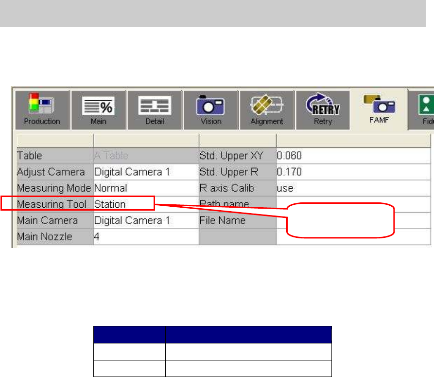
6. Check if the “PCB” is selected from “Measuring tool” item.
When performing ACP, if “Station” is selected from the “Measuring tool” item, it slows the
mounting speed. Please display the FAMF screen and make sure that “PCB” is selected
before performing ACP adjustment.
Figure 47
5.1.4.Preparation for mounting and initial setup
1. Read the board data
The board data varies depends on the glass board used for adjustment.
Glass Board Name of the board
ACP board ACP_1005_10HEAD_FL.ygx
AMFboard ACP_1005_10HEAD__OLD.ygx
Table 21
2. Clamp the glass board.
- Put the double-faced tape on the mounting surface of the board.
- As the board clamp is used for clamping the board, the pushup pins are not necessary.
- Change the board width on the “Unit” screen and clamp the board manually by clicking
on the [Board Clamp] button.
3. Check the “PCB origin”.
Move the camera to the PCB origin coordinate on the “Offset” tab on the “Board” screen, and
check if the Φ.0.5mm mark is near the center. If it is off the center, please adjust the
coordinate by performing teaching.
4. Check the mark information.
Check if the fiducial mark on the glass board can be recognized.
Select the mark No.1 “GlassFid_0.5_Circle” and click on the [MarkAdj] button to check if
the fiducial mark can be recognized.
Check if the mounted ceramic chip component can be recognized.
Affix the ceramic chip on the mounting position on the glass board.
Select the mark No.11 “CERA1005” and click on the [MarkAdj] button to check if the
mounted 1005 ceramic chip can be recognized.
The preparation for ACP adjustment is completed.
Change the setting to
“PCB”.