YS12调整.pdf - 第41页
Service Engineer Service I nformati on SI080 4004 E-000 = YS12 , YG12: Procedure for adjustmen t after installa tion of the mach ine 41/60 If the measured result does n ot meet the specified value: The “X Y offset shif…
Service Engineer
Service Information
SI0804004E-000 = YS12, YG12: Procedure for adjustment after installation of the machine
40/60
6.3 How to analyze the “VgChart”
Please refer to the following for the typical chart of the adjustment result and how to take
measures.
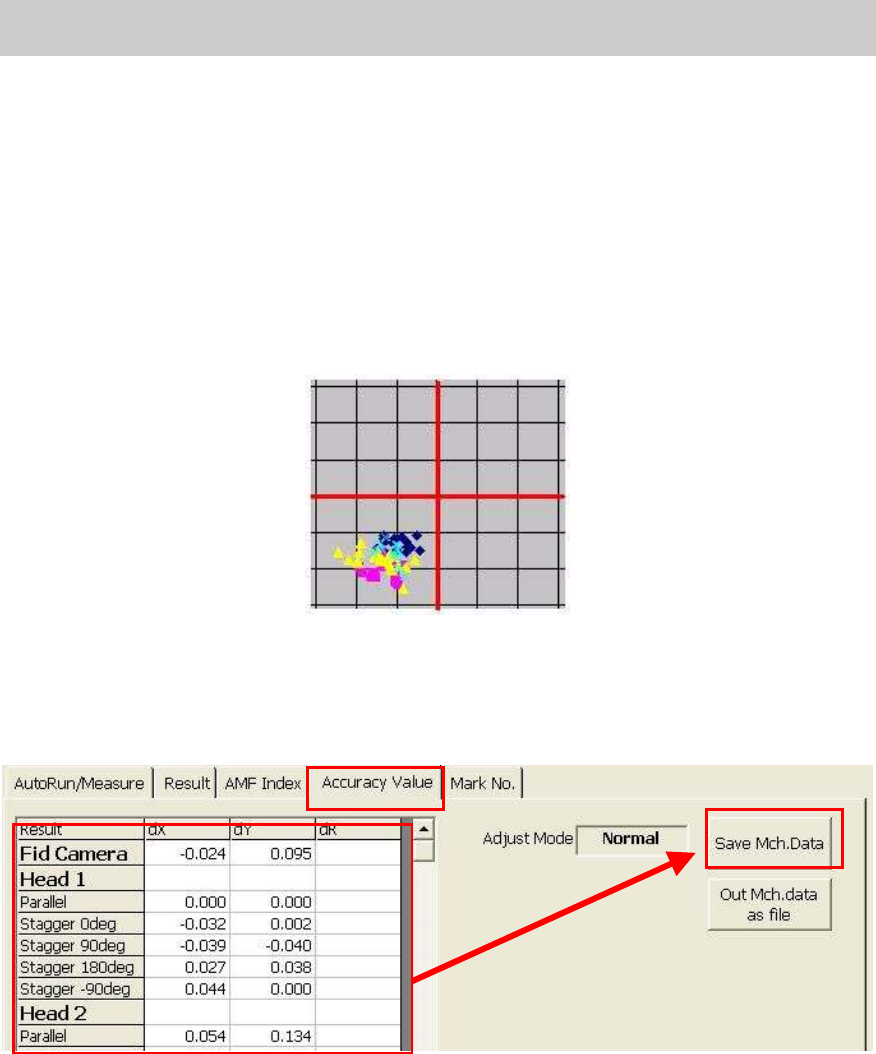
A. If the XY offset shift is found in the data of mounting result
What is “XY offset shift”?
When the deviation is found in the positions where all the components are mounted, in the same
direction and in all the angles as can be seen in Figure 55
.
If the analysis result by the Vg Chart indicates that there is “XY offset shift”, perform feedback for
the compensation value of the measured result.
Figure 55
1. Check and save the corrected value
1) Select the “Accuracy Value” tab.
Click on the “Accuracy value” tab to display the screen shown in Figure 56.
Figure 56
2) Check the values to be corrected.
Check if there is no problem with the values to be corrected, then click on the [Save
Mch.Data] button.
2. After saving the corrected value in the machine data, perform ACP accuracy check again.
If the measured result meets the specified value:
- Bring back the machine data and the data of the mounting result.
- If the machine is equipped with the multi camera Move on to “0.7. Accuracy adjustment
of the multi camera (Option).”
If the machine is not equipped with the multi camera Move on to “8. Items to be adjusted
relating to the mounting accuracy of the machine”.
Service Engineer
Service Information
SI0804004E-000 = YS12, YG12: Procedure for adjustment after installation of the machine
41/60
If the measured result does not meet the specified value:
The “XY offset shift” is supposed to be corrected by performing feedback.
If the result does not meet the specified value, please investigate the cause of the problem
and perform the relevant basic adjustment again.
Please refer to “C. When the variation and the abrupt shift are found in the mounting
result.”
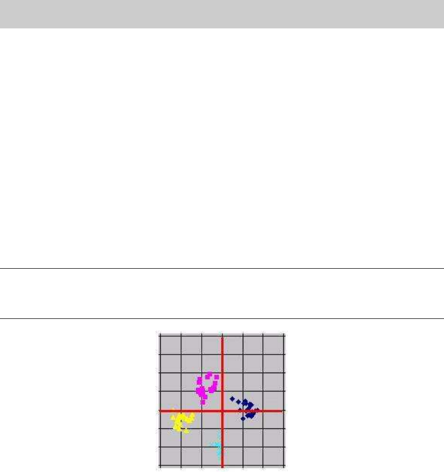
B. If the mounting result data spreads in the X and Y directions
The mounting result data spreads in the X and Y directions in different way depends on the
mounting angle as shown in Figure 57
.
The value of “Index 2” varies depends on the pattern of the mounting result data.
This symptom indicates that some adjustment data may have changed from the factory setting.
Instead of performing feedback (saving the machine data) of the ACP correction value, please
perform readjustment of the following items (check the variation of the data), and then perform
ACP accuracy check again.
Note:
Even when the value of “Index 2” is 1.000 or above, the mounting result data may spread in the X
and Y directions. In this case, please perform feedback of the correction data instead of
readjusting the basic data.
Figure 57
1. Items to be adjusted of the basic data
Please perform adjustment for the following items:
Scale adjustment of the fiducial camera
Scale adjustment of the scan camera
Positioning of the scan camera
Adjustment of the Head Offset XY
If the machine is equipped with the multi camera:
When performing the adjustment of the head offset of the scan camera, the basic data
adjustment of the multi camera needs to be performed. Please perform “Camera scale
adjustment” and “Positioning” of the multi camera after completing the above
adjustments.

Service Engineer
Service Information
SI0804004E-000 = YS12, YG12: Procedure for adjustment after installation of the machine
42/60
2. Perform ACP adjustment
Please make sure to perform feedback for ACP adjustment after readjusting the basic data.
3. Check the accuracy after correcting the data (feedback)
After saving the corrected value in the machine data, perform ACP accuracy check again.
If the measured result meets the specified value:
- Bring back the machine data and the data of the mounting result.
- If the machine is equipped with the multi camera Move on to “0 7. Accuracy adjustment
of the multi camera (Option).
If the machine is not equipped with the multi camera Move on to “8. Items to be adjusted
relating to the mounting accuracy of the machine”.
If the measured result does not meet the specified value:
If the accuracy does not meet the specified value, please investigate the cause of the problem
and perform ACP accuracy check and the relevant adjustment again.
C. When the variation and abrupt shift are found in the mounting result
If the mounting is unstable, the accurate data is not obtained. Therefore, the mounting result
cannot be improved no matter how many times the feedback is performed. Please investigate
the cause of the problem and take relevant measures.
[Items to be checked]
- Is the board clamped properly?
- Is the mark recognition performed with the contaminated mark or insufficient mark
information?
- Is the component supply unit feeding the component properly or the components are
picked up properly?
- Are the components recognized properly?
- Is the nozzle clean or secured properly?
- Are the lens of the camera and the lighting part clean?
- Is the camera mounted properly?
If any problem is detected, please take relevant measures and perform ACP adjustment
again.
When performing adjustment of the board edge clamp unit, the data of the following items
may need to be adjusted.
[Items to be adjusted]
- “PCB Height”
- “Head Offset Z”