FlexSeam Dispensing System Customer Product Manual.pdf - 第24页
Flexseam Dispensing System 20 Part 1127900_01 E 2019 Nordson Corporation Make the Air Supply Connections Using items from the ship‐with kit as needed, make the air supply connections shown in Table 3 and Figure 7. The ai…
Flexseam Dispensing System
19
Part 1127900_01
E 2019 Nordson Corporation
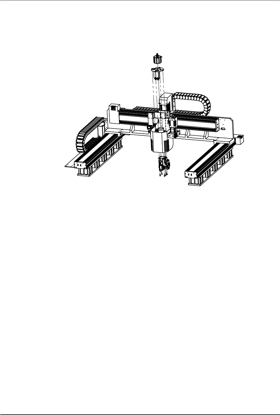
Install the Applicator on the Robot
See Figure 6 for the Flexseam applicators. Use the mounting block and
screws supplied with the applicator to install the applicator on the robot.
Figure 6 Installing a Flexseam applicator on a robot

Flexseam Dispensing System
20
Part 1127900_01
E 2019 Nordson Corporation
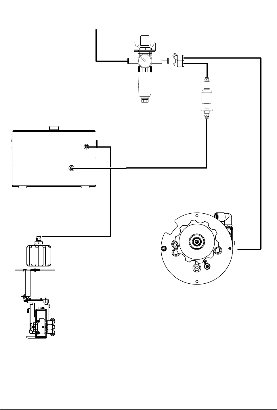
Make the Air Supply Connections
Using items from the ship‐with kit as needed, make the air supply
connections shown in Table 3 and Figure 7. The air supply must be clean,
dry, regulated, un‐lubricated compressed air. Set the operating air pressure
to max 8 bar (116 psi).
Table 3 Air Supply Connections
Item No. in
Fig. 7
Pneumatic Connection Connect to... Then connect to...
1 Main air supply input Main air supply Air regulator input port
2 Air supply to applicator
solenoid valve
Air pressure regulator output
(Y‐fitting)
Air input port on applicator
solenoid valve
3 Air supply to controller
through air dryer
Air pressure regulator output
(Y‐fitting)
Air dryer input/output ports
and controller air input port
4 Air supply to applicator
adhesive syringe or end cap
Air output port on top of
controller
Air fitting on top of
applicator adhesive syringe
or end cap