FlexSeam Dispensing System Customer Product Manual.pdf - 第38页
Flexseam Dispensing System 34 Part 1127900_01 E 2019 Nordson Corporation Check the Applicator Heater NOTE: Cordsets for applicators with a platinum sensor are customer‐supplied. Refer to other documentation as needed. 1.…

Flexseam Dispensing System
33
Part 1127900_01
E 2019 Nordson Corporation
Problem Possible Cause Corrective Action
4. Bead not obvious Low input air supply Ensure that the input air pressure is
greater than 5 bar (72.5 psi).
Old PUR adhesive in system Clean or replace the nozzle, clean the
adhesive path, and/or replace the
module.
Applicator too cold Adjust the temperature setpoint as
necessary.
Change the lip to a larger size.
5. Bead width changes
on the part
Robot speed inconsistent Check the program speed settings.
Applicator position too high/low Check the program height settings
and/or check the height of the product.
6. No adhesive output Low or no input air supply Ensure that the input air pressure is
greater than 5 bar (72.5 psi).
No signal from robot Test the signal using the robot purge
switch. If the applicator purges, the
problem is in the robot. Refer to the robot
product manual to troubleshoot the
robot. If the applicator does not purge,
check the setup.
Solenoid connection lost Check the red light on the solenoid
valve. If the red light is not illuminated,
replace the solenoid.
Old PUR adhesive in system Clean or replace the lip, clean the
adhesive path, and/or replace the
nozzle.
7. Leaks at bleed hole
on module
Adhesive seal failure Replace the module.
Flexseam Dispensing System
34
Part 1127900_01
E 2019 Nordson Corporation
Check the Applicator Heater
NOTE: Cordsets for applicators with a platinum sensor are
customer‐supplied. Refer to other documentation as needed.
1. Disconnect and lock out electrical power to the system.
2. Disconnect the applicator cordset.
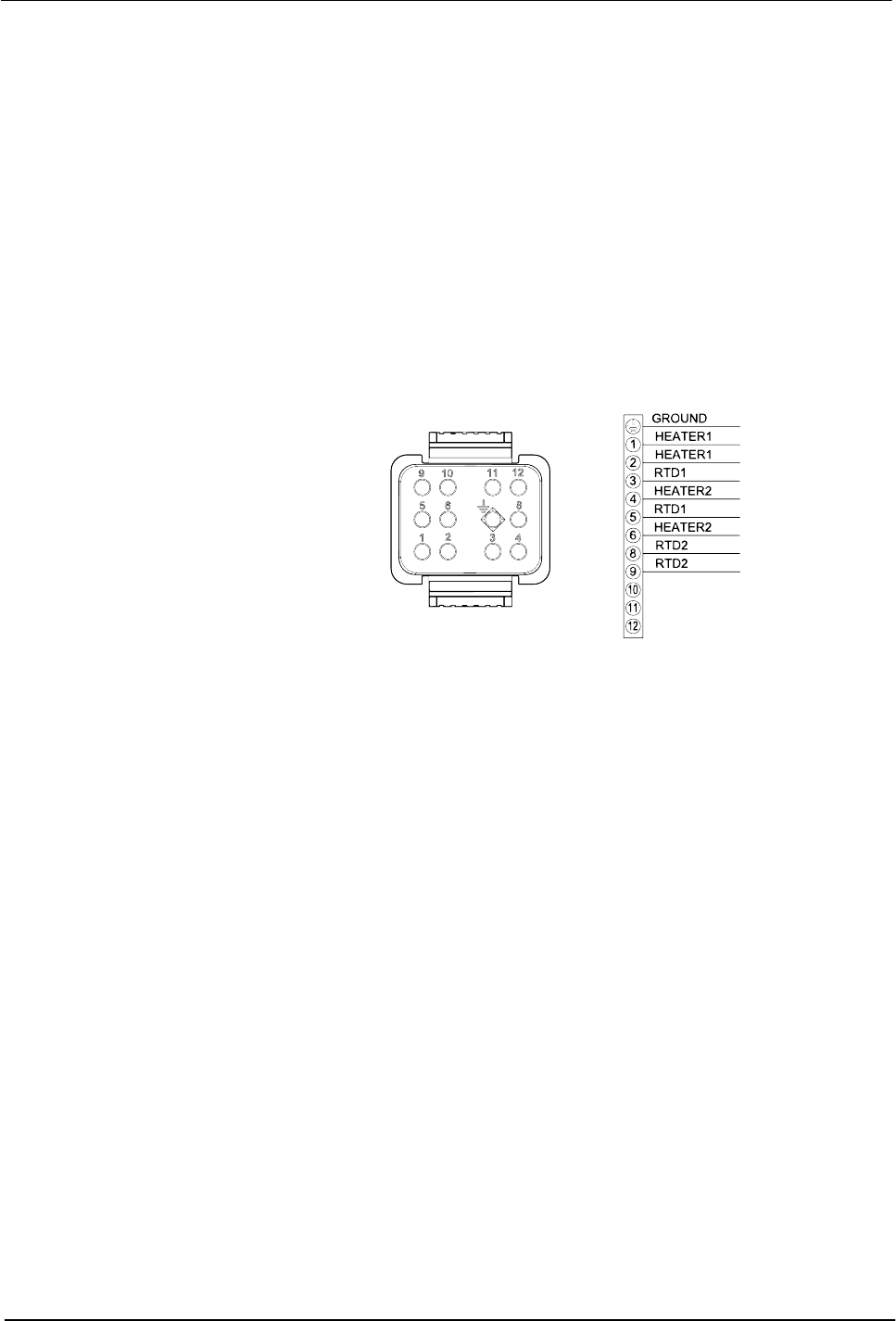
3. See Figure 13. Use an ohm meter to check the heater resistance and
continuity at the heater pins on the cordset:
S If you measure low resistance, the heaters are operating normally.
Return to the procedure that referenced this check.
S If you measure high resistance or if an open circuit is indicated, there
may be a broken wire, a loose connection, or a defective heater.
Continue to the next step.
Figure 13 Pin positions on the applicator cordset
4. Remove the appropriate cordset connector hood and inspect the heater
wiring. Make sure there are no broken wires or loose connections and
that the heaters are wired correctly.
S If any wiring problems are found, correct the problems and restore the
system to normal operation.
S If no wiring problems are found, the heater is probably defective.
Replace the heater.

Flexseam Dispensing System
35
Part 1127900_01
E 2019 Nordson Corporation
Check the Applicator RTD
NOTE: Cordsets for applicators with a platinum sensor are
customer‐supplied. Refer to other documentation as needed.
NOTE: You will need to know the temperature of the RTD to properly
perform this check.
1. Disconnect and lock out electrical power to the system.
2. Disconnect the applicator cordset.
3. See Figure 13. With the RTD at a known temperature, use an ohmmeter
to measure the RTD resistance at the RTD pins on the cordset.
4. See Figure 14 for nickel sensors or Figure 15 for platinum sensors, to
determine the correct resistance of the RTD based on its temperature:
S If the measured resistance is correct, the RTD is operating properly.
Return to the procedure that referenced this check.
S If the measured resistance indicates an open circuit, continue to the
next step.
5. Remove the appropriate cordset connector hood and check for loose
RTD wires or wire connections. Tighten any loose connections.
6. Check the RTD resistance again. If the resistance is normal, the RTD is
now operating properly. If it is not, continue to the next step.
7. Disconnect the RTD wires, measure the resistance across them, and
compare the results to Figure 14:
S If the measured resistance is within the appropriate range, reconnect
the RTD wires, reinstall the cordset connector hood, and return to the
procedure that referenced this check.
S If the measured resistance is not within the appropriate range, replace
the RTD.