FlexSeam Dispensing System Customer Product Manual.pdf - 第39页
Flexseam Dispensing System 35 Part 1127900_01 E 2019 Nordson Corporation Check the Applicator RTD NOTE: Cordsets for applicators with a platinum sensor are customer‐supplied. Refer to other documentation as needed. NOTE:…
Flexseam Dispensing System
34
Part 1127900_01
E 2019 Nordson Corporation
Check the Applicator Heater
NOTE: Cordsets for applicators with a platinum sensor are
customer‐supplied. Refer to other documentation as needed.
1. Disconnect and lock out electrical power to the system.
2. Disconnect the applicator cordset.
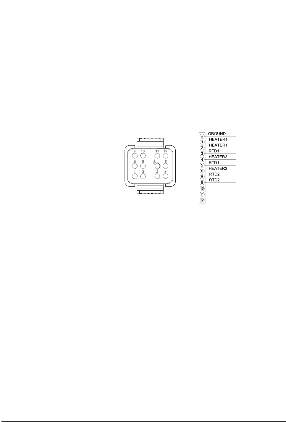
3. See Figure 13. Use an ohm meter to check the heater resistance and
continuity at the heater pins on the cordset:
S If you measure low resistance, the heaters are operating normally.
Return to the procedure that referenced this check.
S If you measure high resistance or if an open circuit is indicated, there
may be a broken wire, a loose connection, or a defective heater.
Continue to the next step.
Figure 13 Pin positions on the applicator cordset
4. Remove the appropriate cordset connector hood and inspect the heater
wiring. Make sure there are no broken wires or loose connections and
that the heaters are wired correctly.
S If any wiring problems are found, correct the problems and restore the
system to normal operation.
S If no wiring problems are found, the heater is probably defective.
Replace the heater.

Flexseam Dispensing System
35
Part 1127900_01
E 2019 Nordson Corporation
Check the Applicator RTD
NOTE: Cordsets for applicators with a platinum sensor are
customer‐supplied. Refer to other documentation as needed.
NOTE: You will need to know the temperature of the RTD to properly
perform this check.
1. Disconnect and lock out electrical power to the system.
2. Disconnect the applicator cordset.
3. See Figure 13. With the RTD at a known temperature, use an ohmmeter
to measure the RTD resistance at the RTD pins on the cordset.
4. See Figure 14 for nickel sensors or Figure 15 for platinum sensors, to
determine the correct resistance of the RTD based on its temperature:
S If the measured resistance is correct, the RTD is operating properly.
Return to the procedure that referenced this check.
S If the measured resistance indicates an open circuit, continue to the
next step.
5. Remove the appropriate cordset connector hood and check for loose
RTD wires or wire connections. Tighten any loose connections.
6. Check the RTD resistance again. If the resistance is normal, the RTD is
now operating properly. If it is not, continue to the next step.
7. Disconnect the RTD wires, measure the resistance across them, and
compare the results to Figure 14:
S If the measured resistance is within the appropriate range, reconnect
the RTD wires, reinstall the cordset connector hood, and return to the
procedure that referenced this check.
S If the measured resistance is not within the appropriate range, replace
the RTD.

Flexseam Dispensing System
36
Part 1127900_01
E 2019 Nordson Corporation
Check the Applicator RTD (contd)
250
240
230
220
210
200
190
180
170
160
150
140
130
RESISTANCE IN OHMS
310
300
290
280
270
260
250
240
230
350
340
330
320
RESISTANCE IN OHMS
TEMPERATURE
TEMPERATURE
16 _C 23 _C 30 _C37 _C44 _C52 _C59 _C 66 _C73 _C81 _C88 _C 95 _C 102 _C 109 _C117 _C
60 _F73 _F86 _F 99 _F112 _F 125 _F 138 _F 151 _F 164 _F 177 _F 190 _F 203 _F 216 _F 229 _F 242 _F
268 _F 281 _F 294 _F 307 _F 320 _F 333 _F 346 _F 359 _F 372 _F411 _F 424 _F 437 _F 450 _F385 _F 398 _F
131 _C 138 _C 146 _C 153
_C 160 _C 167 _C 174 _C 182 _C 189 _C 196 _C 203 _C211 _C 218 _C 225 _C 232 _C
Figure 14 RTD resistance vs. RTD temperature