SIPLACE Vision Customer_en.pdf - 第33页
User Interface Enabling Vision Log Recording Error Analysis Logs S tudent Guide SIPLACE Vision (Customer) Edition 12/2008 EN User Interface 33 4.10.1.2 Vision Meas urement The individual steps and corresponding results f…
User Interface
Error Analysis Logs Enabling Vision Log Recording
Student Guide SIPLACE Vision (Customer)
User Interface Edition 12/2008 EN
32
4.10 Error Analysis Logs
Note: These functions may ONLY be accessed by users with service technician privileges!
4.10.1 Enabling Vision Log Recording
In the pulldown menu View, the user can enable recording of an analysis and result log for Vision
centering and the related error localization procedure. To access the Vision menu, select the operating
mode Setter.
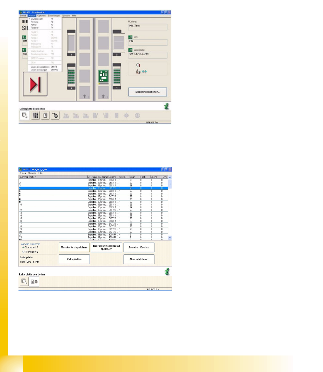
4.10.1.1 Vision Measurement Options
Use this menu to set the Report of measurement results for selected components.
Items in the pulldown menu View:
Vision measuring option – can also be opened
with CTRL + F9.
Vision measurement - can also be opened
with CTRL + F10.
Once a component has been selected in the list,
the buttons will be enabled.
Save measurement context saves the analysis
and results log for this component shape.
No Activity is the default value (no recording is
performed).
Error Save measurement result saves the
centering errors in the analysis and results log
for this component shape (see also the
attached error log).
Delete Selection or Select All are function buttons
for easier selection of the component shape.
User Interface
Enabling Vision Log Recording Error Analysis Logs
Student Guide SIPLACE Vision (Customer)
Edition 12/2008 EN User Interface
33
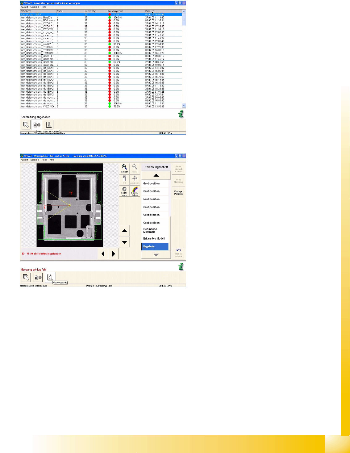
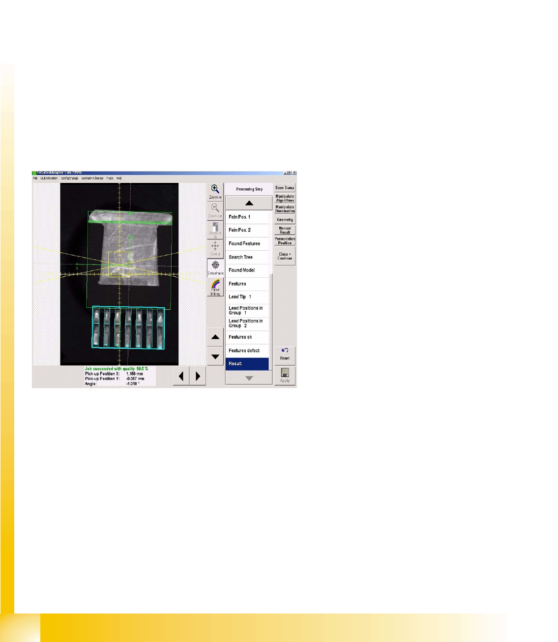
4.10.1.2 Vision Measurement
The individual steps and corresponding results for the optical centering recorded in this error example
can be examined analogous to the analysis surface.
The presentation in the pseudo-colors figure shows the areas of contrast on the component.
The crosshairs show the component pickup offset. Use the zoom function to view details. Each
measurement step and the corresponding result can be viewed in detail in the recognition step menu.
See also:
J
4.10.1.1 Vision Measurement Options [
J
32]
The measurement log shown here is issued when
enabled in Measurement options and can be
called up at Vision measurements, when an error
occurs.
In the menu Display Measurement the individual
measurement steps are shown for the selected
components.
The analysis log in this example shows incorrect
programming of the vectors for corner recognition:
the system tries to locate the light-colored Shield
surfaces to the left of the respective corner
recognition vector.
User Interface
Error Analysis Logs Paths and Settings
Student Guide SIPLACE Vision (Customer)
User Interface Edition 12/2008 EN
34
4.10.2 Paths and Settings
Log folder
The measurement context files are stored in the following folder (for the 6xx SW) on the SC C drive:
C:\Documents and Settings\Operator\Local Settings\Temp\SV Dumps
When using 7xx SW, the following 3 folders are taken: Other dump for machine check / Part dumps for
CSs and PCD dumps for fiducials in C:\SIRIO\Work\SVDumps\
Since SR/MC 603, all selected measurement log files can be saved to any external data carriers from
the menu window, with the
Save As …
command.
Log name
The file names for these recordings are automatically assigned as follows:
Sensor 1033_9-21-02 AM,4.svdmp
If analysis/result log recording is enabled on the Vision interface via Save Dump, the naming schema is
as follows:
PCB-name_CO-name, 9-21-02 AM,4.svdmp
If CO image recording is enabled on the Vision programming interface, the naming schema is as
specified above:
If these log files are opened with the SIPLACE SR
interface CS test menu, the optical centering
results will be displayed, step for step.