SIPLACE Vision Customer_en.pdf - 第99页
Component Shapes Optical Recognition of Free Programmed COs Specific Component Shapes S tudent Guide SIPLACE Vision (Customer) Edition 12/2008 EN Component Shapes 99 Joint datasets with ICOS data NOT possible – Applicabl…
Component Shapes
Specific Component Shapes Components with Open Descriptions
Student Guide SIPLACE Vision (Customer)
Component Shapes Edition 12/2008 EN
98
5.3.13.2 Nonstandard Component Shapes
JEDEC description
Group description
The lead, the (pitch) and pitch tolerance may differ between groups.
Different numbers of leads are permitted.
For groups which are outside the body surface, the maximum group offset is calculated from the
body dimensions and the lead length.
Lead description
Special features
We recommend that you do not disable lead inspection in the geometry data menu, otherwise only
CO position recognition will be performed!
COPLANARITY measurement is possible provided the option has been installed.
SW extensions: FaceDown recognition (See: New Siplace Vision Functions 702).can be programmed
and from SC 702.01 SW (SIPLACE Vision 4.1).
Joint datasets with ICOS data possible –
Applicable if only Gullwing descriptions are used.
Programming steps for definition of CS as Nonstandard class:
If the contact width and lead width vary, COs with this setting
will be classified as Nonstandard CS.
Body description: could be irregular.
The Z-height of the body determines the CO height for the
Z positioning profile and the Z-position for centering with the
stationary camera.
The X/Y body dimensions determine the field of vision, the
Region of Interest.
This component shape may have any of the lead shapes,
including Blobs.
The leads are inside or outside the body surface.
Notches may be programmed, to help correctly determine
the lead position, even in this extreme case.
The lead recognition filter should be set so that the notch for
the Gullwing or Wraparound leads is not measured.
The system does not actively search for these notches i.e. does
not check their presence. Instead, the lead end is recognized in
its actual position through the modified filter.
All combinations of lead, Balls and Blobs are possible, with
various dimensions, offsets and pitches.
Blobs are programmed with rewritten (modified) rectangles.
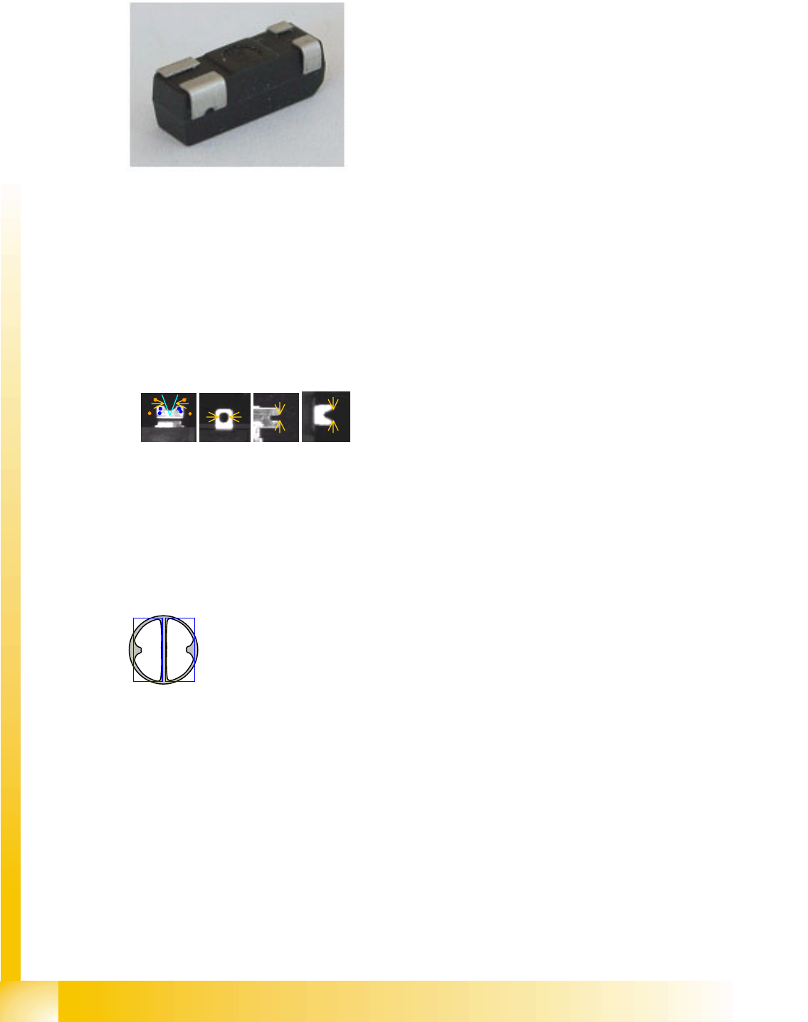
The camera image of some COs is one bright, round spot.
In this case, the CO body needs to be defined as a vertical
cylinder and the lead as a column.
Component Shapes
Optical Recognition of Free Programmed COs Specific Component Shapes
Student Guide SIPLACE Vision (Customer)
Edition 12/2008 EN Component Shapes
99
Joint datasets with ICOS data NOT possible –
Applicable if SIPLACE Vision uses one of its own special recognition procedures (e.g. for corners or
special lead shapes).
5.3.14 Optical Recognition of Free Programmed COs
The Nonstandard centering procedure determines the CO center position from the recognition steps
required for the individual lead. This involves both coarse and fine measurement. Component inspection
can also be enabled or disabled, as required.
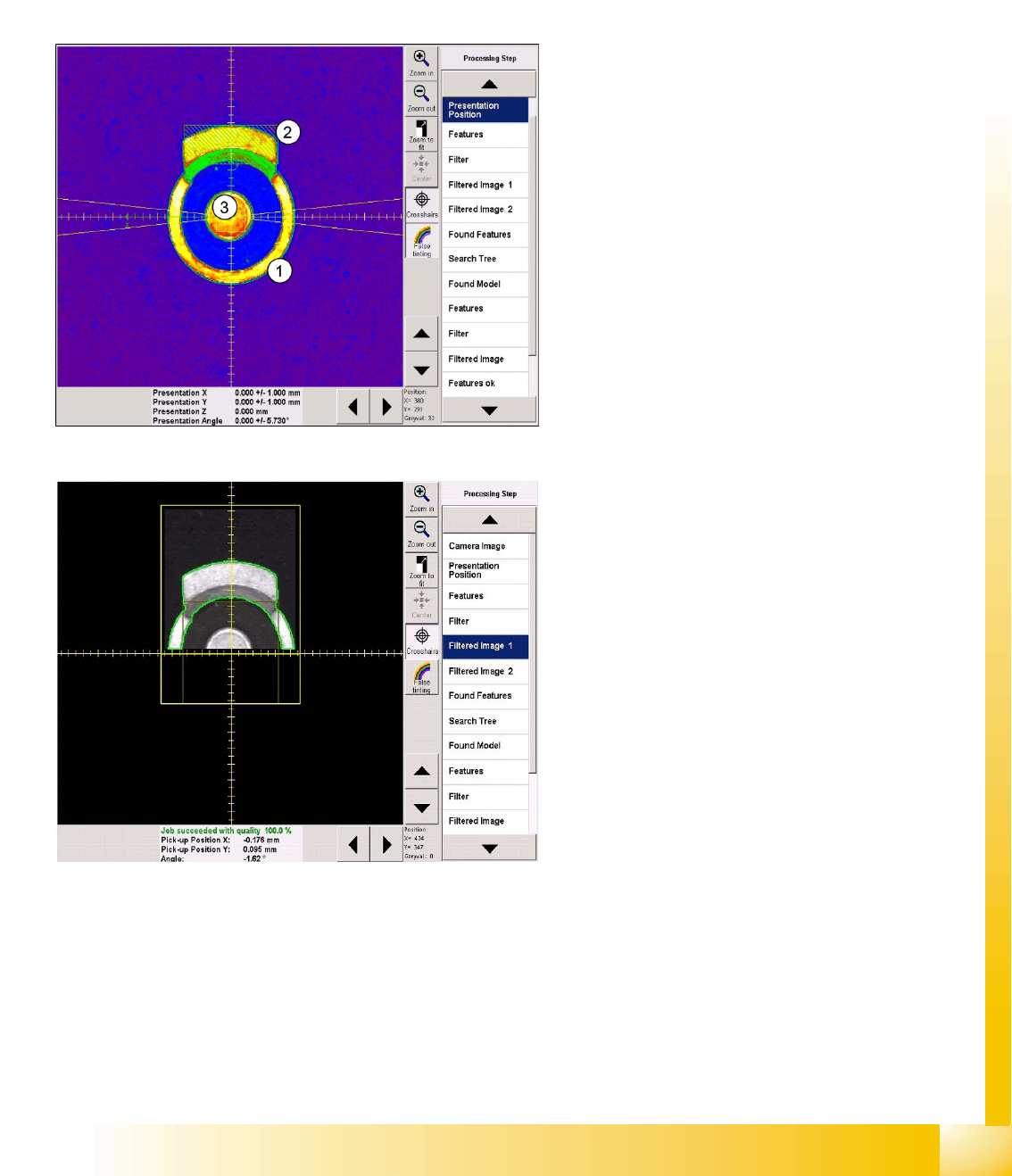
Recognition step Presentation position
This CS is programmed as a vertical cylinder (1).
The diameter is the outer diameter of the ring
(indicated by the green dotted line).
The first lead group is the metal flag pointing
upwards (2), programmed as a Blob.
The second lead group is the circular central lead
(3), programmed as a Ballcircle.
As usual, the presentation position (white dotted
cross), CO X/Y coordinates (green arrows) and
the permitted angle tolerance are entered here but
will not all be visible in the printout.
Recognition step Filter 1
The lead type Blob is a rectangle with dimensions
of 2.5 x 6.3 mm. This defines the lead center,
which is taken as the basis for the Blob lead (bright
shape) search region and forms the focus of this
shape.
The search region for the second lead group is
marked as a dark square in the evaluation image
for the first group.
Component Shapes
Specific Component Shapes Optical Recognition of Free Programmed COs
Student Guide SIPLACE Vision (Customer)
Component Shapes Edition 12/2008 EN
100
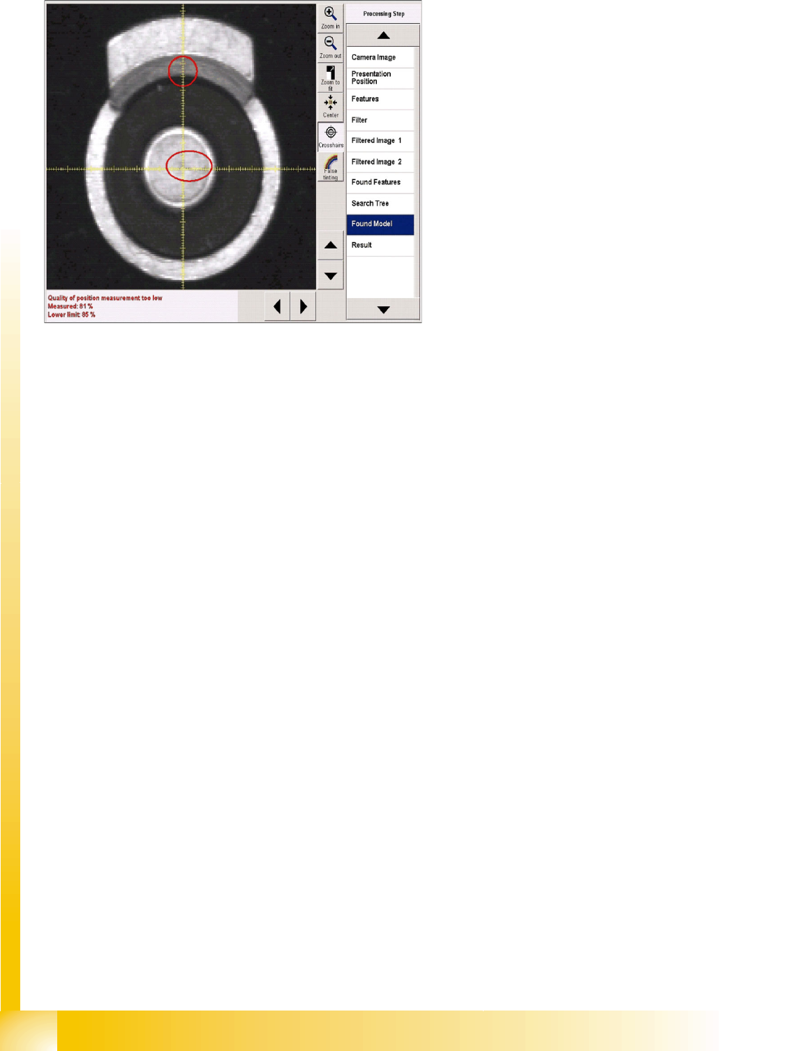
Error processing
If error messages are issued during the
recognition steps, the error reason will be
displayed in the results window, under the camera
image.
IN a corresponding recognition step, the
evaluation will be omitted (red rings) and the
steps for the subsequent component inspection
will not be available in the selection menu.