SIPLACE Vision Customer_en.pdf - 第48页
Component Shapes Component Shape Description Rules Key Placement Accuracy Points S tudent Guide SIPLACE V ision (Customer) Component Shapes Edition 12/2008 EN 48 5.2.2 Key Placement Accuracy Point s When describing compo…
Component Shapes
Lead Shapes Component Shape Description Rules
Student Guide SIPLACE Vision (Customer)
Edition 12/2008 EN Component Shapes
47
The group offset from the body center to the center of the lead group is specified for components with
lead groups.
The reference point for group descriptions is the body center *, as this is calculated during optical
centering for the so-called Best Placement and is then moved by the machine into the placement
position.
A group offset is specified as the distance from the body center to the group center.
When the group center is positioned on a CO symmetry axis, one of the X or Y offset values will be equal
to 0.
Blob: Electromechanical
nonstandard
Irregular lead surfaces with non-assignable geometry. These
are described by a rectangle enclosing them.
Polygon circle: Shields / Socket
(Nonstandard)
Circles are specified as Polygon circles (multiple corners
such as circles), since the circle is depicted with the use of
tangents.
Corners: Shields
(Nonstandard)
Corners on the Shield edges or on the unleaded CO sides of
nonstandard/Socket shapes.
The virtual leads displayed by ICOS and the arrows shown
in the SIPLACE Vision depiction of corners are both marked
in the CS.
Pins with notch Nonstandard only Lead evaluation filters are not set for the notch region.
Centering pins
(for SIPLACE Vision only)
Nonstandard only The height of the centering pin is added to the component
height without leads. Optical recognition is not performed. (In
future SW versions, the centering pin height could also be
used for slow position of the Z axis down.)
Rectangle
(from 702 SIPLACE Vision
4.1 only)
Nonstandard only Rectangular features visible with the illumination for lead
features can be an additional help for optical centering. This
might even be the entire component outline.
Legend
1. Group 1 offset
2. Group 2 offset
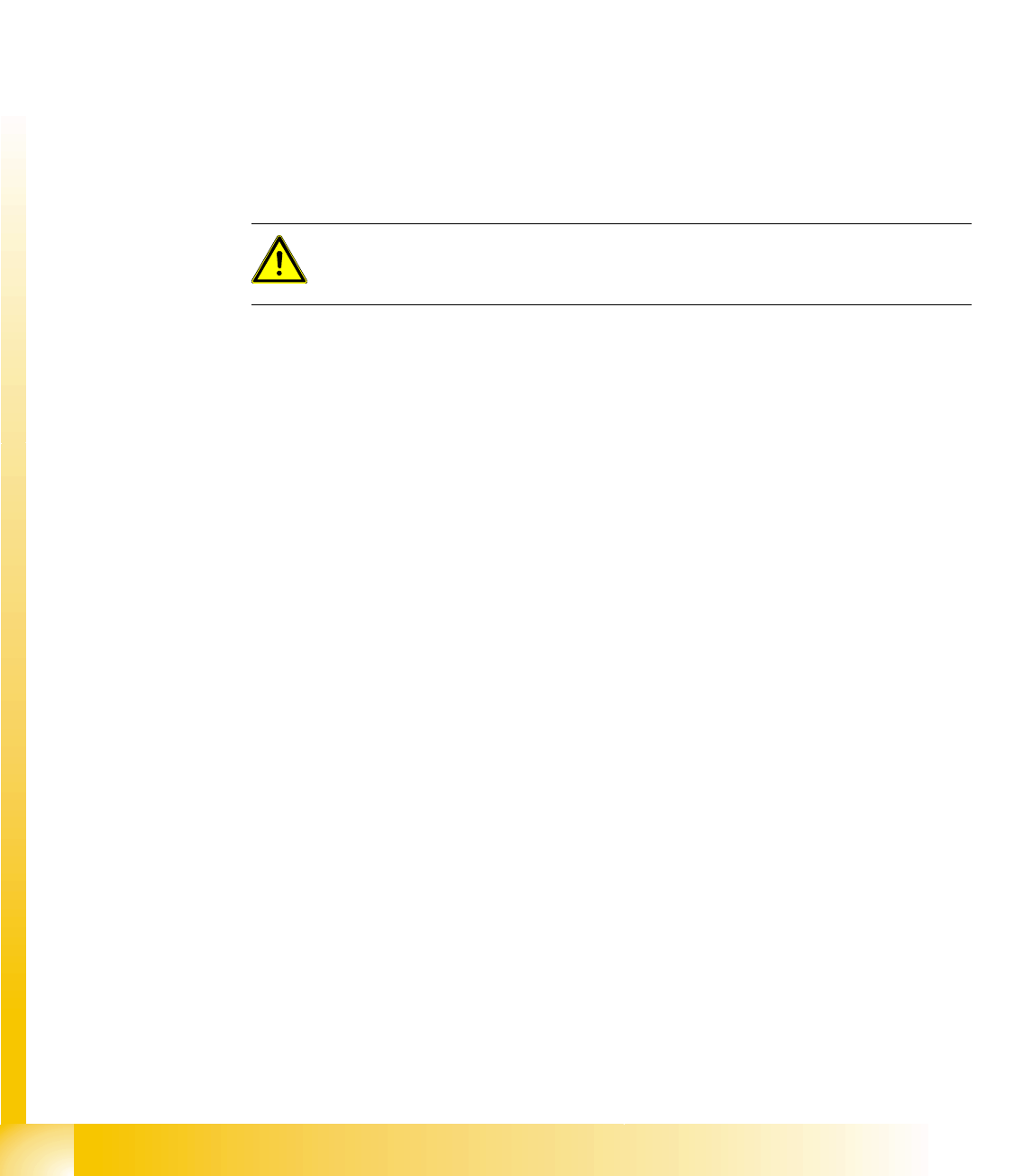
The group offset from the body center to the center of the lead group is specified for
components with lead groups. However, these groups can be outside the CO symmetry
axes, in which case neither the X or Y offset values will be equal to 0.
Note: The component pickup point can be separately programmed in SIPLACE Pro 3.x.
This involves programming the pickup coordinates to the body center (for both Vision
systems).
In the case of special shapes (e.g. single-row component shapes), take care that the
values for the lead group offsets are correct. To ensure that the CO is correctly picked
up by the feeder, you need to also program an eccentric position in the feeder.
Lead shape Typical CO Comment / special features
1 2
Component Shapes
Component Shape Description Rules Key Placement Accuracy Points
Student Guide SIPLACE Vision (Customer)
Component Shapes Edition 12/2008 EN
48
5.2.2 Key Placement Accuracy Points
When describing component shapes, observe the following points for correct placement:
The group offsets describe the offset for a group of visible features, on the basis of which the body
center is calculated for the placement procedure. Make sure that the group offsets have the same
values for all components which are symmetrical to the center axes.
The correct offset values will need to be calculated for those components which are not
symmetrically aligned around the center axes (see D-Packs). In this case, the body dimensions
should reflect the actual dimensions, to simplify evaluation of CS tests.
The measurement analysis shown on the screen helps you to assess whether the group offset
values really have the correct dimensions to the body center, thereby ensuring placement accuracy.
ALWAYS check that placement on the board is accurate, as the CAD layout system generally
determines the placement coordinates symmetrically to the center of the pad positions on the PCB.
When programming, we recommend that you first correct the CS dimensions and then shift these
onto the outer edges of the body. Subsequently, check the lead lengths and group offsets with the
help of the evaluation diagram and the correlation with the camera image.
Inspection mode allows shape-specific tests, such as the evaluation of body sizes in SIPLACE Vision
(ICOS systems only check this parameter with a SIZE measurement). This prevents COs (Chip
shape) from being placed in an upright position. For this test to work, make sure that the CO body
dimensions have been described correctly and the tolerance description is precise (the lead
dimensions are also processed in inspection mode for molded shapes)!
The lead spacing is also checked for all Leaded component shapes.
5.2.3 Processing Data
When programming the camera, do not forget to set the max. field of vision (FOV) data and the
smallest possible lead/Ball structure or smallest pitch (see camera overview at the end of this
document).
The C&P nozzles have various lengths, so that the bottom edge of the CO can be optimally
positioned in the focal range of the placement head CO camera. A deviation from this is calculated,
displayed and taken into account in the measurement algorithm with C&P head component cameras.
For optimum processing of COs during the placement procedure, the acceleration and delay values
can be reduced for all axes.
In addition, the pick and place procedure can be optimized by selecting one of the various positioning
profiles for the Z-axis (Pickup - contactless; Placement - with very high force; Placement - slow
braking; Slow start;...).
Components smaller than 6 mm should be processed with the pickup mode Early Vacuum .
Feeder data can be set as default data for the CS (pickup offset ; pickup tolerance; CO availability
time (waiting time ) for the feeder pitch; COs per reel;...). If feeder information has been programmed
for a CO, this will be prioritized for the setup.
If the pickup tolerance data from the feeder is specified illogically high, this could have a negative
effect on the measurement procedure (feature search range will be too great).
ATTENTION:
Shifting the group offset values means that the centering procedure in the ICOS
system will now apply a placement offset identical to the value entered.

Component Shapes
Unleaded Component Shapes Specific Component Shapes
Student Guide SIPLACE Vision (Customer)
Edition 12/2008 EN Component Shapes
49
5.3 Specific Component Shapes
The following pages describe the key component shapes with programming information for SIPLACE
Vision.
The last item in each case, dataset, refers to the SIPLACE Pro option in which datasets for SIPLACE
Vision and the older ICOS Vision systems can be managed separately. The Requires separate group
description checkbox creates separate folders for these datasets. Only enable this checkbox if you are
unable to assign separate descriptions to these datasets. Using this option too often will increase your
data management work.
5.3.1 Unleaded Component Shapes
Definition
Components, which have no leads or which have leads situated inside the body dimensions, will be
specified as unleaded shapes in this section.
In these cases, SIPLACE Vision will not perform lead measurement (exception: extensions 702 SW).
From SC/MC 702 (SV 4.0.1) (see: New SV functions 702), BareDie and molded components can
also be used for face down recognition (non-specific component features), in addition to the CHIP
components.
CHIP and molded CSs have an additional lead length inspection.
Measurement procedure
The component position and angle at the nozzle are determined through gradient formation and various
other steps. In a second step, the body dimensions are determined through gradient formation and other
measurement steps.