SIPLACE Vision Customer_en.pdf - 第90页
Component Shapes Specific Component Shapes Optical Re cognition of Hemispherical Leads S tudent Guide SIPLACE V ision (Customer) Component Shapes Edition 12/2008 EN 90 Component inspection process Features searched for A…
Component Shapes
Optical Recognition of Hemispherical Leads Specific Component Shapes
Student Guide SIPLACE Vision (Customer)
Edition 12/2008 EN Component Shapes
89
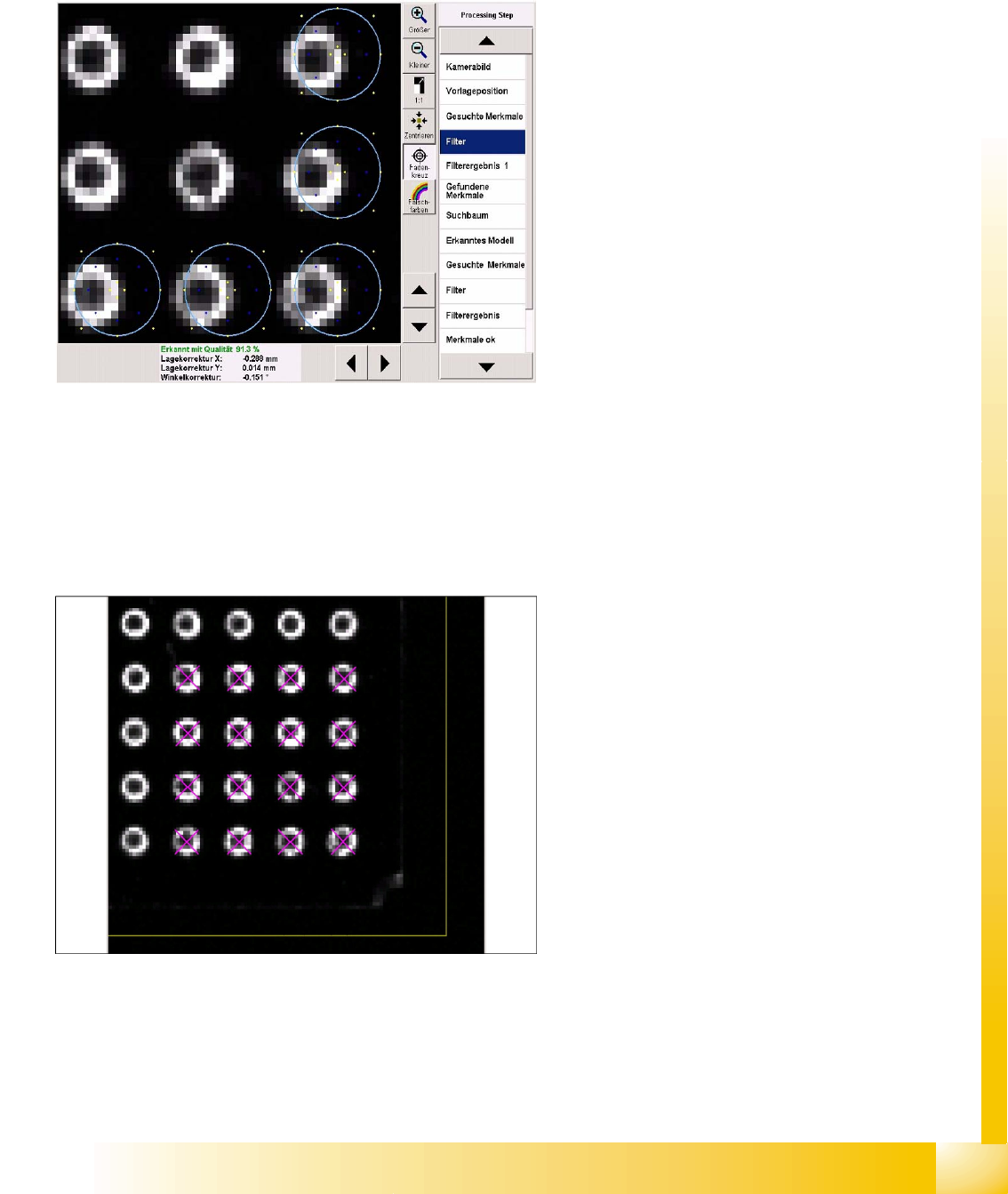
5.3.10 Optical Recognition of Hemispherical Leads
The BGA centering procedure determines the CO center position, based on the data from ball
recognition with
A.) Pre-centering and
B.) Component inspection of ball lead.
Filter for pre-centering at the CO corners
Five ball leads are searched for in each CO
corner. These 20 features facilitate fast and
accurate determination of the CO position.
Template filter in the bottom right CO corner.
The light blue ring shows the programmed ball
diameter.
The typical representation of a ball is the ring-
shaped reflection from flat illumination.
The required filters show two dark areas.
The yellows points on the outside show the CO
body.
The blue points show the reflecting sides of the
ball lead.
The yellow points on the inside show the flat
part of the ball lead.
Do not enable steep illumination for hemispherical
leads, since the missing balls will not be
recognized in this case i.e. metallic lead surfaces
without balls would be displayed identically.
Ball leads in the corner region
Component Shapes
Specific Component Shapes Optical Recognition of Hemispherical Leads
Student Guide SIPLACE Vision (Customer)
Component Shapes Edition 12/2008 EN
90
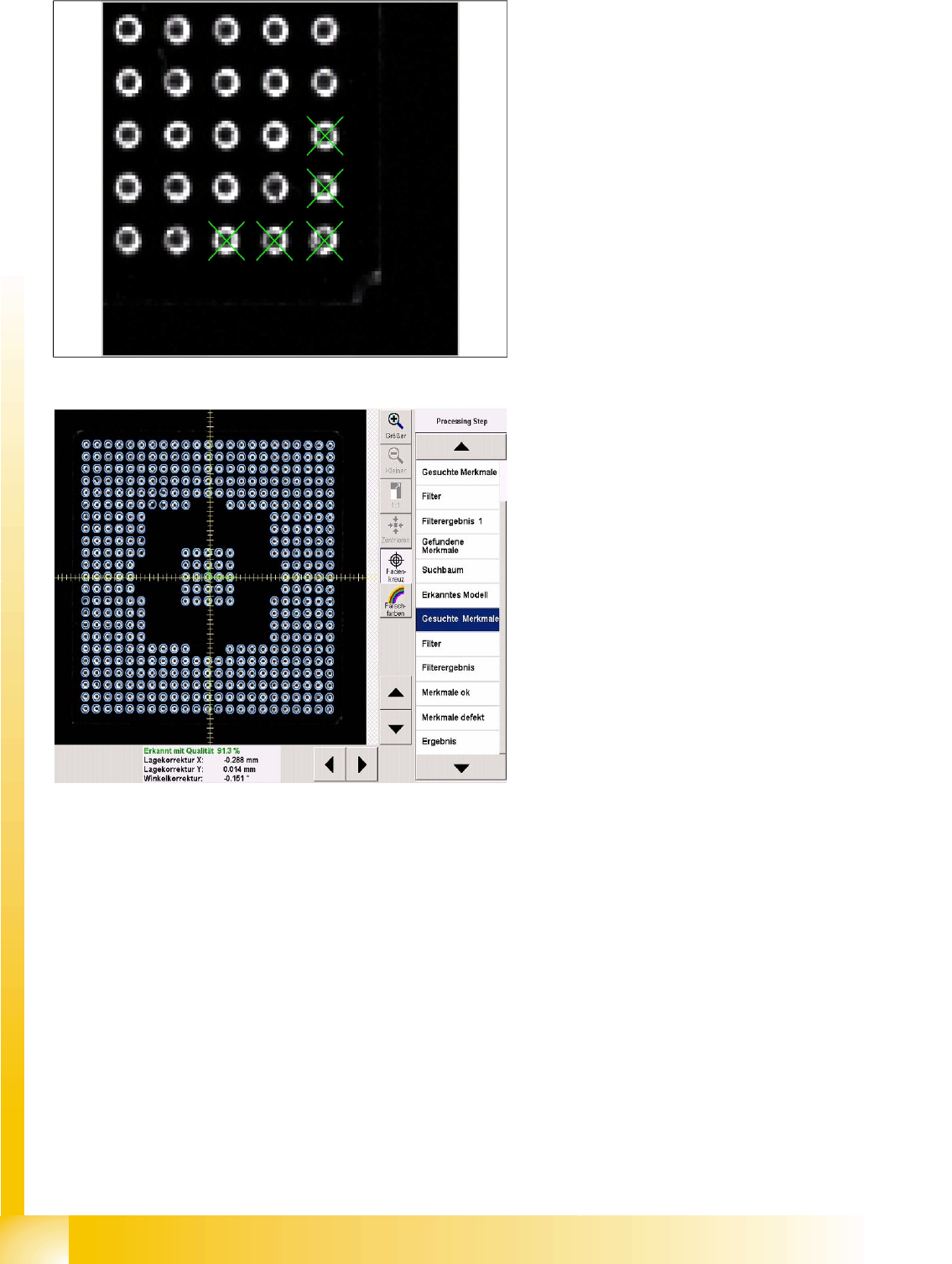
Component inspection process Features
searched for
All balls enabled during programming will be
inspected with the above mentioned filter.
If a particular ball does not achieve the required
quality, this will be shown in the Feature faulty
menu.
Filter 22 is used to process CCGA components.
This filter does not have the central, dark point.
Circles in Shield programming are processed with
filter 32.
Component Shapes
Shields Specific Component Shapes
Student Guide SIPLACE Vision (Customer)
Edition 12/2008 EN Component Shapes
91
5.3.11 Shields
Since corners could be recognized on shields or frames, components of this type are defined in a
separate class. The pseudo description of leads on the shield body edges (as in ICOS) is therefore not
required.
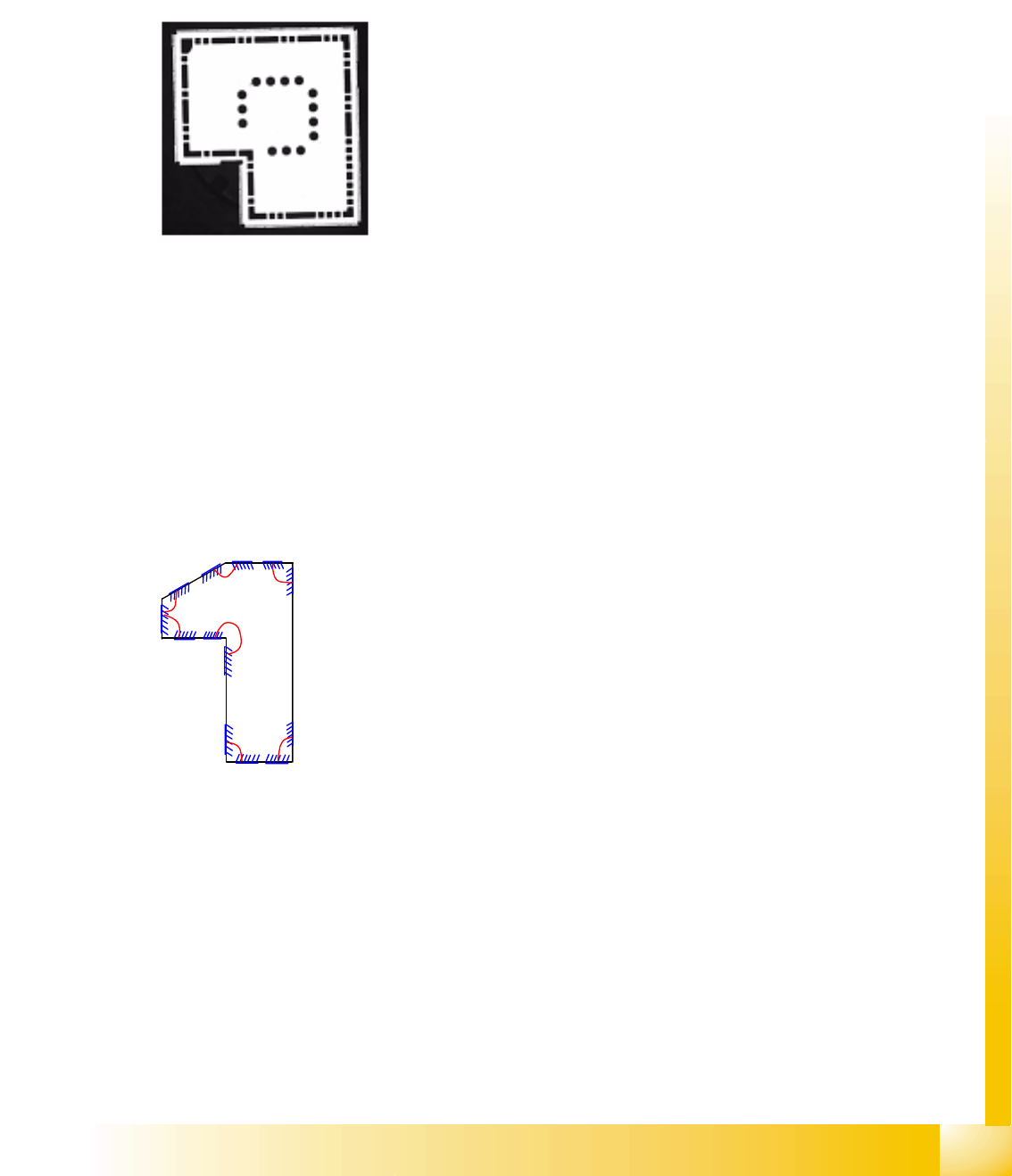
5.3.11.1 Shield Component Shape
JEDEC description
JEDEC description
One or more groups are possible, with more than four corners. A group angle or X and Y group offset
does not need to be defined. In the type Corner, each starting or end point of the two corner lines is
defined with X and Y coordinates.
The shortest length of the corner line is 1.8 mm (depending on the camera). Reliable distribution of
measurement points can not be guaranteed below this.
At least two recognized corners are needed to center a Shield.
Additional descriptions are permitted, with one circle per group.
Group description
Body description: polygons are permitted as body shapes for
Shields (an all-enclosing rectangle is easier to program!).
The Z-height of the body determines the CO height for the
Z positioning profile and the Z-position for centering with the
stationary camera.
The X/Y body determines the size of the field of vision,
known as the Region of Interest and the rectangular outline
of the Shields.
Lead type corner or polygon circle.
The leads are positioned within the body. The feature angle
is always 0°. The setting Hell can be set to Dark for circles.
To recognize corners, a recognition field is drawn to the left
of the programming line, for the trimming the Shield. The
two vectors should have roughly the same lengths. Circle
programming is performed according to the principle for
BGA ball leads. However, recognition of polygon circles
uses a totally different method.
The diagram only shows the different, possible corners;
NEVER program so many (3-4 is ALWAYS sufficient).