SIPLACE Vision Customer_en.pdf - 第46页
Component Shapes Component Shape Description Rules Lead Shapes S tudent Guide SIPLACE V ision (Customer) Component Shapes Edition 12/2008 EN 46 5.2.1 Lead Shapes The lead shapes generally have predefine d English names. …
Component Shapes
Overview of Component Shapes Which Require Separate Group Descriptions Component Shape Description Rules
Student Guide SIPLACE Vision (Customer)
Edition 12/2008 EN Component Shapes
45
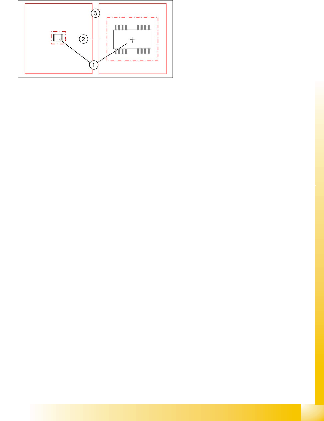
The X/Y body dimensions
The X/Y body dimensions are now understood to be dimensions for the plastic body (1).
Based on the calculated overall body dimensions, the camera field of vision (2) or so-called Region
of Interest (ROI) is set.
The component tolerance and packaging tolerance are taken into account in this calculation.
The component body is not measured optically. The dimensions are only needed to produce a
diagram for better assessment.
Angle of component
CS testing is normally performed at a definition angle of 0°.
However, the presentation angle can be adjusted in 90° steps for CS testing at any heads.
The optical centering of components is always performed in the pickup position when using DLM
C&P6/12 heads.
Optical centering for Twin heads is performed in the placement angle (next possible 90° angle).
When using the C&P20 head, optical centering is performed in the placement angle (next possible
90° angle).
Polarity detection - inspection mode
SC Bearbeitung des Kamerabildes 02 0305 SIPLACE Vision supports Pin 1 detection, provided
optically recognizable asymmetries have been programmed.
The selection of inspection mode in SIPLACE Pro applies only to SIPLACE Vision (not for older
Vision systems).
The programmed polarity parameters are shown in the board or setup CO displays, in graphics
mode. However, this does not affect the measurements in the Vision system.
Lead lengths
Provided the leads are aligned towards the outside, the lead lengths are added together with the body
dimensions to give the overall dimensions of the component shape. The overall dimensions can be
viewed in the component shape geometry menu. These values can not be edited.
Once the body dimensions for unleaded CSs have been successfully measured, you can generally
assume that the component has been correctly recorded and that it is not in an upright position or
tipped to one side on the nozzle.
Legend
1. X/Y dimensions of component body (without
leads)
2. Restricted camera search field, so-called.
Region of Interest (ROI)
3. Camera field of vision
Component Shapes
Component Shape Description Rules Lead Shapes
Student Guide SIPLACE Vision (Customer)
Component Shapes Edition 12/2008 EN
46
5.2.1 Lead Shapes
The lead shapes generally have predefined English names.
Gullwing, J-Lead, Wraparound, Ball (for BGAs) and Column are the most common examples.
Lead angle
The lead angle is the angle at which the lead protrudes from the component body. Leads which point
towards the Y-axis (upwards) have an angle of 0°, although 90° was defined in the line computer CS
Editor.
The lead angle specified in SIPLACE Vision depends on the lead type. You need to specify the position
of the lead end.
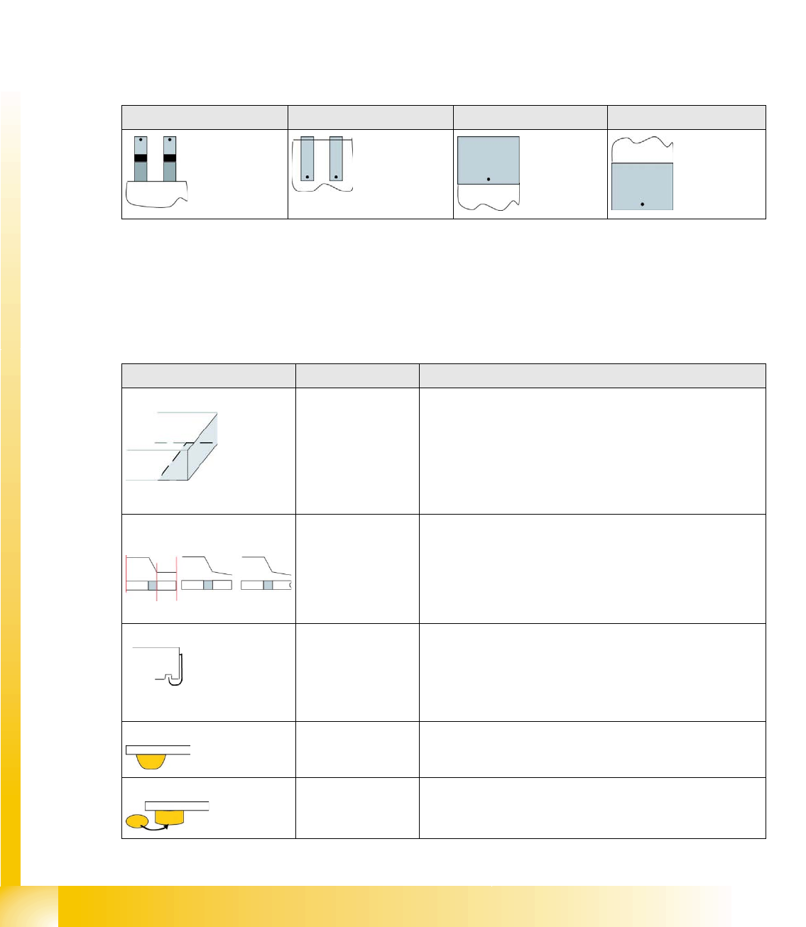
The diagrams below each show the edge of a component body, with leads. The orientation of the lead
end in its 0° position is marked with a dot.
Blob - special features
The Blob (binary large object ) stands for a lead shape or structure which is saved as a graphic. It can
not be adequately described with the typical dimensions (e.g. lead width and length). In this case,
SIPLACE Vision automatically determines the characteristic contours for measuring the structure.
Overview of lead shapes
Gullwing: J-Lead: Wraparound: Blob:
Lead shape Typical CO Comment / special features
Wraparound: Chip / Melf /
(Moulded)
The surface or metal surface (often as wide as the body) of
this lead shape is folded around the edge of the component
(except with the type Moulded).
Wraparounds are defined only by the visible lead length. This
can be dark or bright!
The ends of the Wraparounds may contain notches, see
Gullwing.
Gullwing: Soxx / QFP The JEDEC description JESD30-B applies for this lead
shape. This indicates a thin lead, which is curved from the IC
surface to the contact surface. The contact length is always
shorter than the lead length. The ends of the Gullwing leads
may contain notches, in which case the CO can be described
as nonstandard.
J-Lead: PLCC / SOJ The J-shaped pins are curved into cavities under the body
surface. Only select this if the pins have the correct shape. J-
Leads are defined only by the visible lead length.
Balls: BGA Hemispherical leads under the CO body surface.
Columns: CCGA Column-shaped lead points under the component body
surface.
Component Shapes
Lead Shapes Component Shape Description Rules
Student Guide SIPLACE Vision (Customer)
Edition 12/2008 EN Component Shapes
47
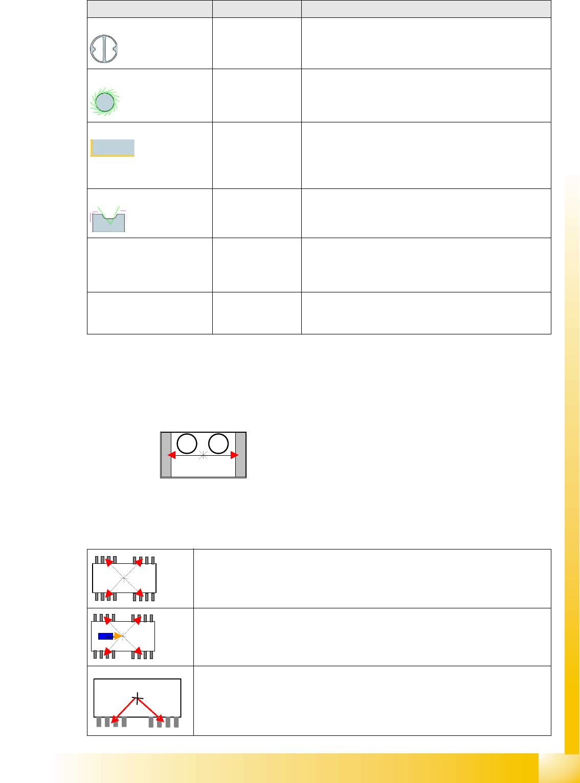
The group offset from the body center to the center of the lead group is specified for components with
lead groups.
The reference point for group descriptions is the body center *, as this is calculated during optical
centering for the so-called Best Placement and is then moved by the machine into the placement
position.
A group offset is specified as the distance from the body center to the group center.
When the group center is positioned on a CO symmetry axis, one of the X or Y offset values will be equal
to 0.
Blob: Electromechanical
nonstandard
Irregular lead surfaces with non-assignable geometry. These
are described by a rectangle enclosing them.
Polygon circle: Shields / Socket
(Nonstandard)
Circles are specified as Polygon circles (multiple corners
such as circles), since the circle is depicted with the use of
tangents.
Corners: Shields
(Nonstandard)
Corners on the Shield edges or on the unleaded CO sides of
nonstandard/Socket shapes.
The virtual leads displayed by ICOS and the arrows shown
in the SIPLACE Vision depiction of corners are both marked
in the CS.
Pins with notch Nonstandard only Lead evaluation filters are not set for the notch region.
Centering pins
(for SIPLACE Vision only)
Nonstandard only The height of the centering pin is added to the component
height without leads. Optical recognition is not performed. (In
future SW versions, the centering pin height could also be
used for slow position of the Z axis down.)
Rectangle
(from 702 SIPLACE Vision
4.1 only)
Nonstandard only Rectangular features visible with the illumination for lead
features can be an additional help for optical centering. This
might even be the entire component outline.
Legend
1. Group 1 offset
2. Group 2 offset
The group offset from the body center to the center of the lead group is specified for
components with lead groups. However, these groups can be outside the CO symmetry
axes, in which case neither the X or Y offset values will be equal to 0.
Note: The component pickup point can be separately programmed in SIPLACE Pro 3.x.
This involves programming the pickup coordinates to the body center (for both Vision
systems).
In the case of special shapes (e.g. single-row component shapes), take care that the
values for the lead group offsets are correct. To ensure that the CO is correctly picked
up by the feeder, you need to also program an eccentric position in the feeder.
Lead shape Typical CO Comment / special features
1 2