SIPLACE Vision Customer_en.pdf - 第92页
Component Shapes Specific Component Shapes Shields S tudent Guide SIPLACE V ision (Customer) Component Shapes Edition 12/2008 EN 92 Corner description Joint datasets with ICOS data NOT pos s ible due to new recognition m…
Component Shapes
Shields Specific Component Shapes
Student Guide SIPLACE Vision (Customer)
Edition 12/2008 EN Component Shapes
91
5.3.11 Shields
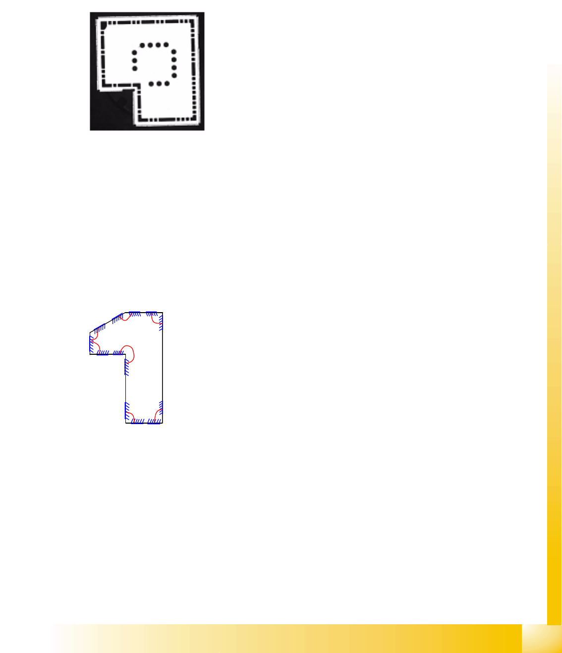
Since corners could be recognized on shields or frames, components of this type are defined in a
separate class. The pseudo description of leads on the shield body edges (as in ICOS) is therefore not
required.
5.3.11.1 Shield Component Shape
JEDEC description
JEDEC description
One or more groups are possible, with more than four corners. A group angle or X and Y group offset
does not need to be defined. In the type Corner, each starting or end point of the two corner lines is
defined with X and Y coordinates.
The shortest length of the corner line is 1.8 mm (depending on the camera). Reliable distribution of
measurement points can not be guaranteed below this.
At least two recognized corners are needed to center a Shield.
Additional descriptions are permitted, with one circle per group.
Group description
Body description: polygons are permitted as body shapes for
Shields (an all-enclosing rectangle is easier to program!).
The Z-height of the body determines the CO height for the
Z positioning profile and the Z-position for centering with the
stationary camera.
The X/Y body determines the size of the field of vision,
known as the Region of Interest and the rectangular outline
of the Shields.
Lead type corner or polygon circle.
The leads are positioned within the body. The feature angle
is always 0°. The setting Hell can be set to Dark for circles.
To recognize corners, a recognition field is drawn to the left
of the programming line, for the trimming the Shield. The
two vectors should have roughly the same lengths. Circle
programming is performed according to the principle for
BGA ball leads. However, recognition of polygon circles
uses a totally different method.
The diagram only shows the different, possible corners;
NEVER program so many (3-4 is ALWAYS sufficient).
Component Shapes
Specific Component Shapes Shields
Student Guide SIPLACE Vision (Customer)
Component Shapes Edition 12/2008 EN
92
Corner description
Joint datasets with ICOS data NOT possible due to new recognition methods
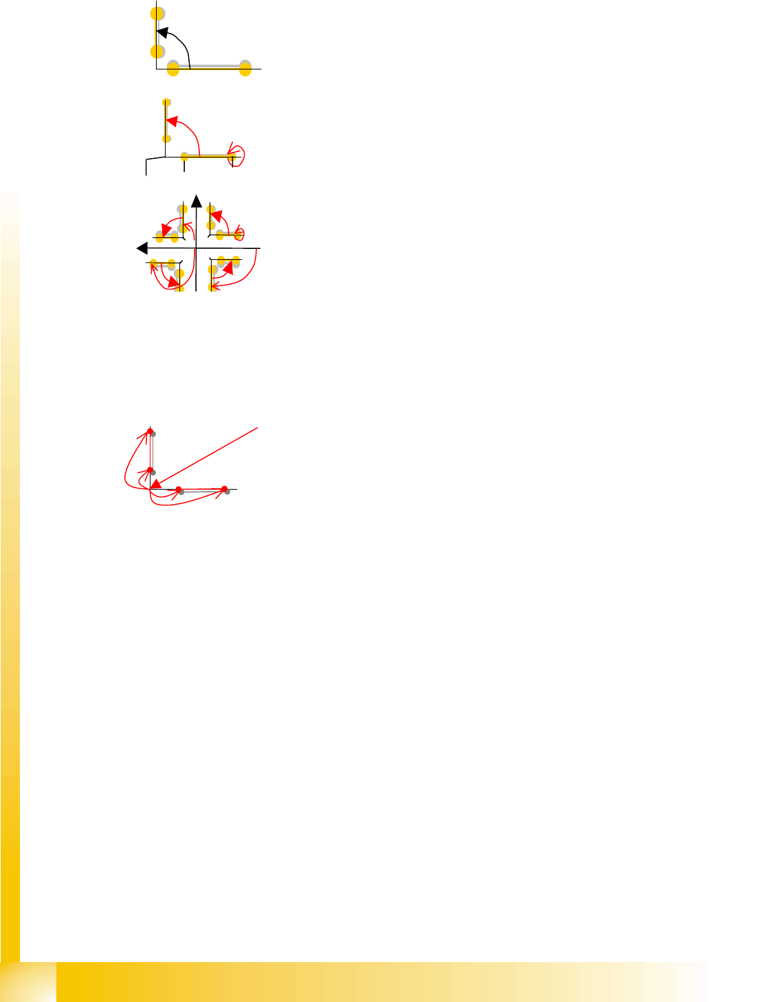
There are inner and outer corners:
The 1st programming type SV defines each starting and
end point with X/Y coordinates.
Due to the possible radiuses or recesses in the corners, the
recognition lines are not placed right into the corners of the
Shield!
This coordinate data is also stored in SIPLACE Pro.
The 2nd programming mode radius can also be taught
online. In this case, the corner coordinates; the opening
angle of the 1st recognition line to the X body axis; the
distance of the recognition vector to the corner (radius 1/2)
and its length are programmed. The radius dataset is then
converted.
The coordinate or radius dataset is most effectively
calculated by using the mouse to mark the corners. Ensure
an accurate fit, as the coordinate values will later determine
the placement accuracy! The body dimensions must be
correct and match those in the teaching template.
The illumination/evaluation ensures that these corners can
be recognized.
Corner programming in SIPLACE Pro can be performed
with eight X/Y coordinates for the respective corner
recognition starting and end points.
The procedure for 90° corners is somewhat simpler in
SIPLACE Pro: In tis case, the center point -> corner
coordinates are programmed and the eight corner
characteristic coordinates are then programmed based on
this corner (four of these coordinates are always 0).
In the case of corners which do not have 90°, the simplest
method at the moment is to program in SIPLACE Vision, at
the station and using point, line or radius programming in
teach mode.
Punkt 1.1
nicht prog. (90°)
Punkt 1.2
Punkt 2.1 Punkt 2.2
Öffnungswinkel
90°
Eckenw.=0°
Radius1 Länge1
Eckpunkt X/Y
A
ussenecken
+Y
-90° Eckenwin.=0°
+X 180° 90°
Component Shapes
Shields Specific Component Shapes
Student Guide SIPLACE Vision (Customer)
Edition 12/2008 EN Component Shapes
93
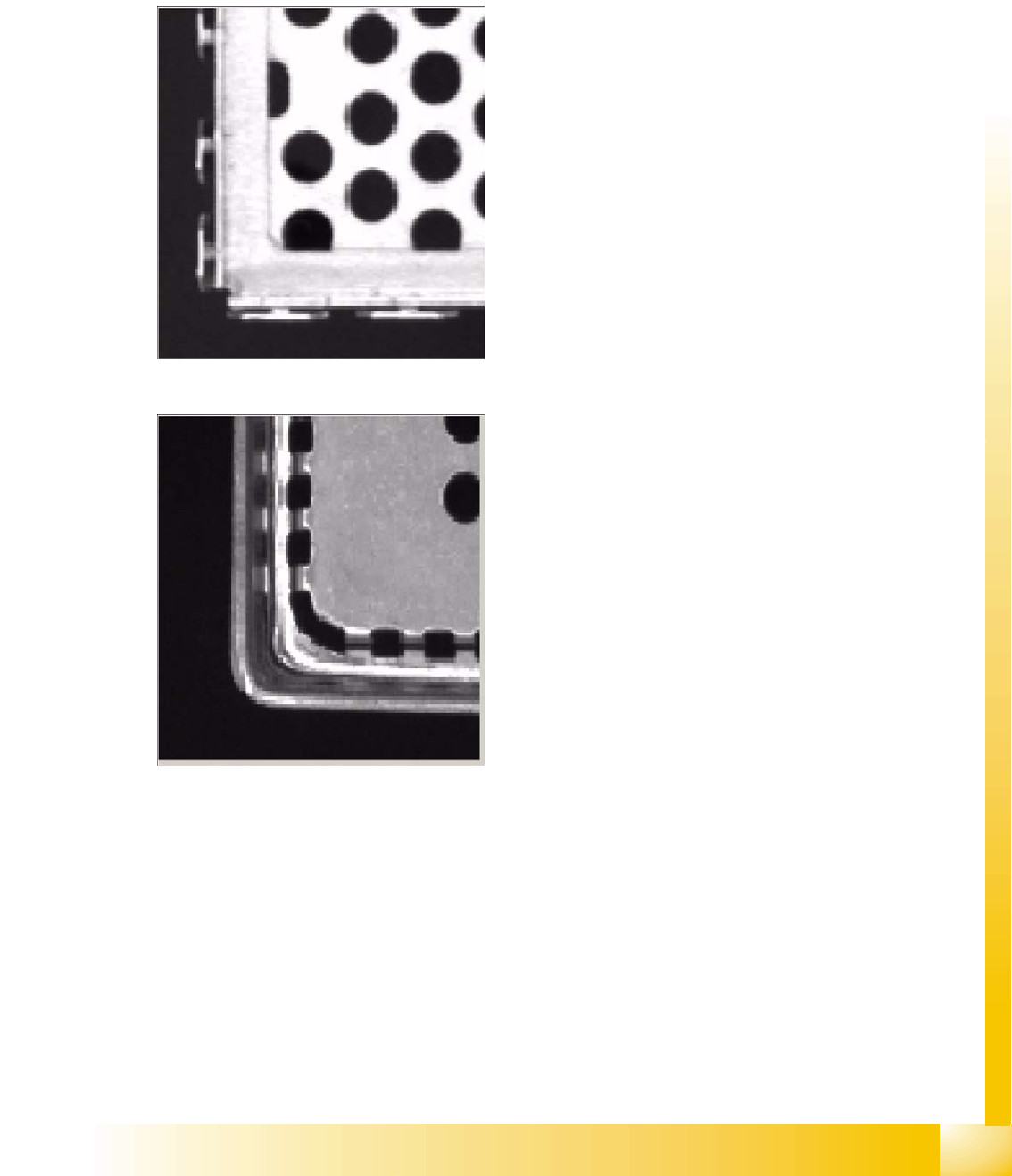
5.3.11.2 Special Features for Shields
Shields are sheet metal with curved edges in a wide range of body shapes, some with openings/
holes drilled through; inner and outer corners and various opening angles.
The evaluation times increase with the programmed angle tolerances.
Various corner filters: four corner filter types are possible, depending on the different shield edges
used.
Filter type 248 e.g. for edge springs;
Default setting: Several position candidates
are permitted for each edge, although each
candidate must be above the gradient
threshold. Each edge is also subjected to an
additional scan. This singles out poor quality
edges, primarily candidates caused by
springs.
Filter type 249, for good edge quality;
Outer edge: Always takes the outermost
position (as seen when looking from outside
the component) above the gradient threshold
(in the case of double edges, caused by
indentations in the Shield and steep
illumination). The system only considers
edges which are within the yellow search
frame.