SIPLACE Vision Customer_en.pdf - 第84页
Component Shapes Specific Component Shapes Optical Re cognition and Evaluation of Leaded COs S tudent Guide SIPLACE V ision (Customer) Component Shapes Edition 12/2008 EN 84 Lead inspection of tab (heat sink) i n recogni…
Component Shapes
Optical Recognition and Evaluation of Leaded COs Specific Component Shapes
Student Guide SIPLACE Vision (Customer)
Edition 12/2008 EN Component Shapes
83
5.3.8.2 Recognition of Very Wide Leads
Heat sink (tab) and ground connection leads are often produced as overwide leads. They need to be
included in the programming, otherwise the angle calculation step will deliver incorrect results, if there
are too few leads on the opposite side or if the lead rows are too short.
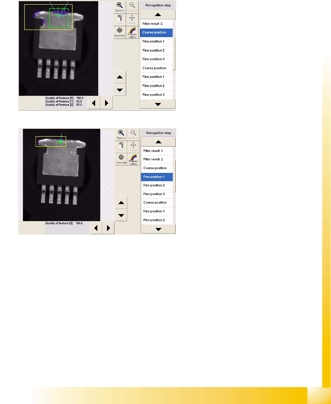
Recognition step Coarse position 1
This step measures the outer edges (1) with the
help of brightness evaluation, performed vertically
to the lead in the region around the light blue Vs.
This step also determines the lead center (2) at the
outer edge in the left measurement window (the
same procedure is used for coarse/fine position 2
in the right-hand window).
Finally, the left side edge is determined. The
procedure here is to set the image point pairs so
low that the normal slant of the side edge is not
included in the measurement.
Recognition step Fine position 1
Several point pairs are now used to determine a
fine position and fine angle, within the position
defined during the step Coarse position1.
As described for SO components, the same
process is applied to the leads in group 2.
Lead inspection is then performed for the
recognized lead positions.
Component Shapes
Specific Component Shapes Optical Recognition and Evaluation of Leaded COs
Student Guide SIPLACE Vision (Customer)
Component Shapes Edition 12/2008 EN
84
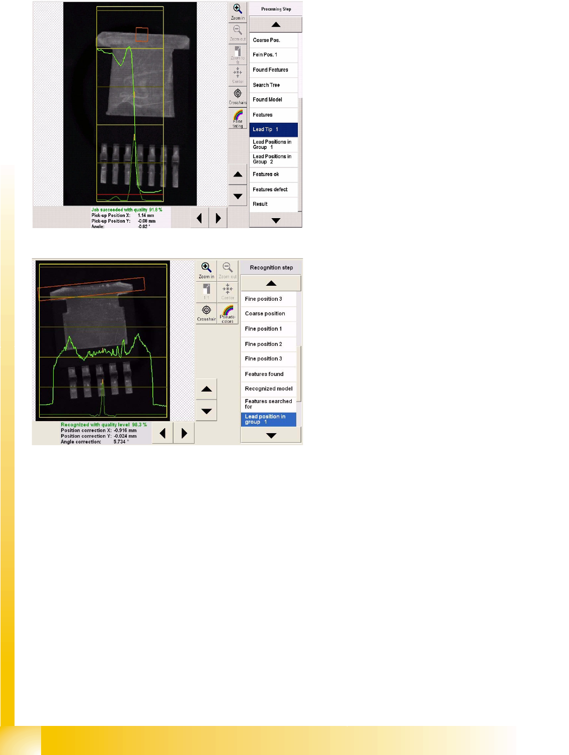
Lead inspection of tab (heat sink) in
recognition step Lead tip1
The yellow areasmark the results window (1)
with brightness and gradient characteristics.
The red measurement window is where the
brightness is determined from bottom to top. This
is then entered in the results window (light green)
from left to right.
The brightness gradient (alteration) is used to
calculate the position of the lead outer edge
(orange).
Lead inspection of tab (heat sink) in
recognition step Lead width1
The system scans the red measurement window
in a horizontal direction, searching for regions of
brightness (light green ). The evaluation and
marking of results will be displayed accordingly, as
in the diagram.
Lead inspection is performed as described for SO
components.
Component Shapes
Components With Round Leads Specific Component Shapes
Student Guide SIPLACE Vision (Customer)
Edition 12/2008 EN Component Shapes
85
5.3.9 Components With Round Leads
Ball Grid Arrays or Ceramic Column Grid Arrays have various round connection points under the body
surface. In the initial step, up to 20 features are applied in the CO corners, to determine the coarse and
fine positions (including the angle). The recognized CO position and angle are then checked to ensure
that all leads are present and in the correct position on the grid.
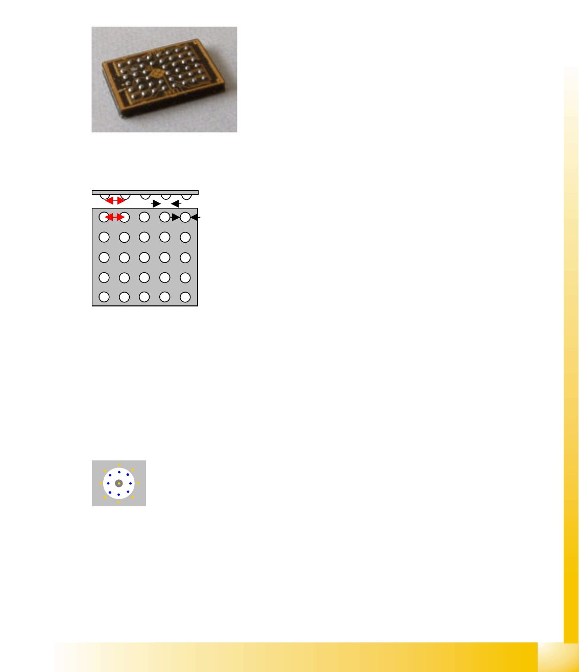
5.3.9.1 BGA Component Shape (Ball Grid Array / FlipChip)
JEDEC description
JEDEC description
Lead description
The leads are distributed throughout the CO surface, as hemispherical contacts which are arranged
in a matrix . This component shape has so-called Ball leads.
The ball diameter and ball tolerance must be identical for all groups.
Special features
The ball quality is set to only 66%, due to the ceramic BGAs. For a reliable ball check on normal BGAs,
we recommend raising this value to 70-80% in the algorithm menu.
Joint datasets with ICOS data possible –
(see MS-034)
Body description: rectangular.
The Z height of the body determines the CO height for the
Z positioning profile.
The X/Y body dimensions determine the field of vision, the
Region of Interest.
The body size should be adjusted to reflect the real body
size and not just cover the size indicated by the ball leads.
This component shape has hemispherical leads arranged
in columns and rows. It can contain one or more groups.
Leads may be missing in the rows or columns.
The (pitch) and pitch tolerance for the ball arrangement
must be identical in all groups.
The pitch is greater than the ball diameter, even with
individual balls.
The contrast between the body and the Ball lead can be set
as required. Normally, the Ball lead is brighter than the
body.
The standard flat illumination for BGAs only illuminates the
hemispherical Ball leads and not the flat connection circles
on the body. A special filter has been programmed for this
purpose.
You can also select an option for inspection of ball
presence and arrangement.