SIPLACE Vision Customer_en.pdf - 第36页
User Interface Component Shape Wizard Creating Component Shapes S tudent Guide SIPLACE V ision (Customer) User Interface Edition 12/2008 EN 36

User Interface
Creating Component Shapes Component Shape Wizard
Student Guide SIPLACE Vision (Customer)
Edition 12/2008 EN User Interface
35
4.11 Component Shape Wizard
From SW version 603.01, the Component Shape Editor in SIPLACE Pro features a component shape
creation feature at the station, for teaching component shapes.
This is a camera-supported, semi-automatic function for creation of component shapes (CS), which still
allows the programmer to make the final decision about values which influence quality.
4.11.1 Creating Component Shapes
To create component shapes (CS), there is a manual programming function with camera support at the
station and a CS wizard tool. This CS wizard does not provide all possible CS types but only supports
the following selection for complex lead arrangements:
ECV
SOXX, SOT, DPACK, QFP
SOJ, PLCC
BGA/FlipChip, CCGA
Shield
Socket, connector, nonstandard
Further CS-types have to be programmed manually.Simple rules, which are allocated to the component
shape, are used to reduce programming to a minimum.
BareDies consist only of the body dimensions, which can be programmed with length and width (plus
the corresponding tolerances). (The Z height can only be changed in SIPLACE Pro.)
CHIP and MELF consist only of bodies with attached wraparound leads. Once the body length and width
and the lead length (and tolerance) are defined, everything has been programmed. (The leads are as
wide as the body. The offset of the lead groups is calculated from the body length and lead length).
When using shapes of the type "molded", the lead width also needs to be programmed, in addition to the
dimensions required for CHIP types. This is because the leads are narrower than the body width.
The programming process with the CS wizard ALWAYS involves AN image recording. Teaching with the
CS wizard can therefore NOT be interrupted or continued for adding further lead features to existing
programming.
At the end of programming or teaching with the wizard, each CS needs to be centered multiple times.
The aim is to test whether the X/Y and angular values are found to be stabile. This test should be
performed at different angles and in various positions, to make sure that subsequent placement does
not randomly fail at different positions. An even better method is to perform optical recognition with
various different components.
It may be helpful to run a robustness test, which is integrated from station SW 605.01 or from teach
station SW 604.01 for SIPLACE Vision.
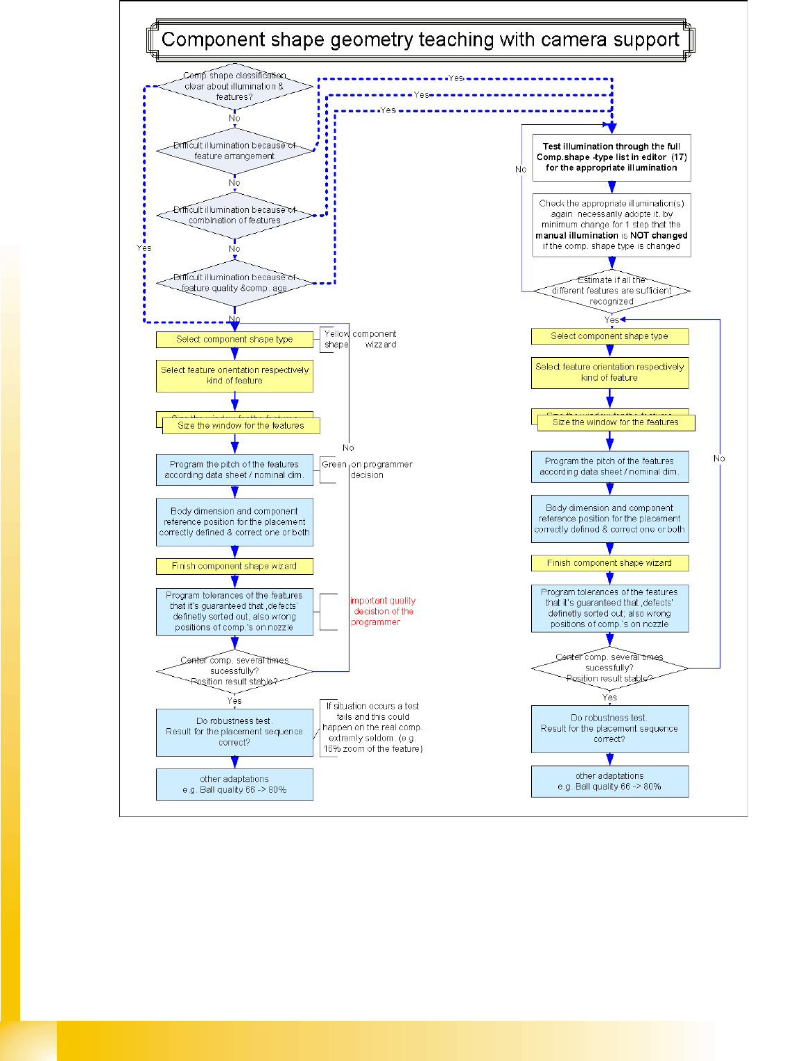
The following diagram shows an easy procedure in order get a good illumination also in case of difficult
CS.
User Interface
Component Shape Wizard Creating Component Shapes
Student Guide SIPLACE Vision (Customer)
User Interface Edition 12/2008 EN
36

User Interface
Quality-Influencing Decisions Component Shape Wizard
Student Guide SIPLACE Vision (Customer)
Edition 12/2008 EN User Interface
37
4.11.2 Quality-Influencing Decisions
1.) The lead grid dimensions
During the teaching of lead features, the programmer will be requested to make a decision about the grid
size of the lead group.
The measured grid for the group and 1 or 2 suitable nominal grid sizes will be prompted (e.g. 1.25 mm
(metric) and 1.27 mm). This needs to be programmed by taking into account the data on the data sheet
and will influence quality. The measured size may not be used to artificially raise the quality level, as this
is based on possible distortions to the teaching sample.
2.) Component shape center and body size
The Component shape center calculated during teaching is presented for a decision to the
programmer, as this is the component position which, together with the placement coordinates, will later
determine the placement accuracy for this component. Do not confirm this query without careful
consideration and always perform test placement if the components are extremely asymmetrical or
lopsided.
The body size is a value which is not used in the measurement procedure. However, it can help the
operator to recognize the component shape or assess the centering result (e.g. for shield components).
For this reason, the body size should be adjusted here to the actual dimensions of the (normally) dark
body.
3.) Tolerances
The tolerances for the nominal dimensions are set to low values by the CS wizard. ONLY YOU can
decide whether these are right for your components, based on your knowledge of the components
concerned and the requirements of your assemblies. ALWAYS check these tolerances AFTER teaching.
When using special component shapes, such as socket, connector and nonstandard, this also applies
to the programmed nominal dimensions, as leads of the same type could be dimensioned differently in
other groups.