SIPLACE Vision Customer_en.pdf - 第75页
Component Shapes Leaded Component Shapes Specific Component Shapes S tudent Guide SIPLACE Vision (Customer) Edition 12/2008 EN Component Shapes 75 5.3.7.5 SOxx Component Shape (Small Outline xx) JEDEC description Group d…
Component Shapes
Specific Component Shapes Leaded Component Shapes
Student Guide SIPLACE Vision (Customer)
Component Shapes Edition 12/2008 EN
74
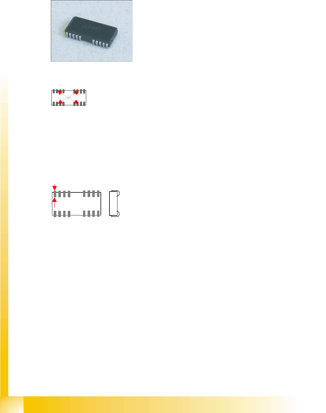
5.3.7.4 SOJ Component Shape (Small Outline J-Lead)
JEDEC description
Group description
Lead description
Special features
The component belongs to the SO class of components, although it is separately classified for the
illumination and filter settings.
Inspection of the lead number, position and pitch is set as a default for these leads and can not be
disabled.
We do not recommend selecting the COPLANARITY measurement option for this component
shape, since the hemispherical connection surfaces prevent reliable measurement results.
J-Leads should only be programmed when the component shape is really a J-Lead, otherwise
recognition errors could occur.
Joint datasets with ICOS data possible!
Body description: rectangular.
The Z height of the body determines the CO height for the
Z positioning profile.
The X/Y body dimensions determine the field of vision, the
Region of Interest.
The overall body outline is determined by the J-Lead leads.
This component shape has two (or more) lead groups on
the two component sides, meaning that the CO must be
asymmetrical to the body axes.
More than one group can be located on one CO side.
The leads in the groups must be identical, although their
numbers may differ!
The lead pitch and pitch tolerance must be identical in all
groups.
This component shape has so-called J–Leads, i.e.. leads
curved under the component body, in the form of a J.
These leads are defined by the lead length and width.
The leads are inside the body surface. Notches can not be
programmed.
The leads are aligned towards the body center line.
Component Shapes
Leaded Component Shapes Specific Component Shapes
Student Guide SIPLACE Vision (Customer)
Edition 12/2008 EN Component Shapes
75
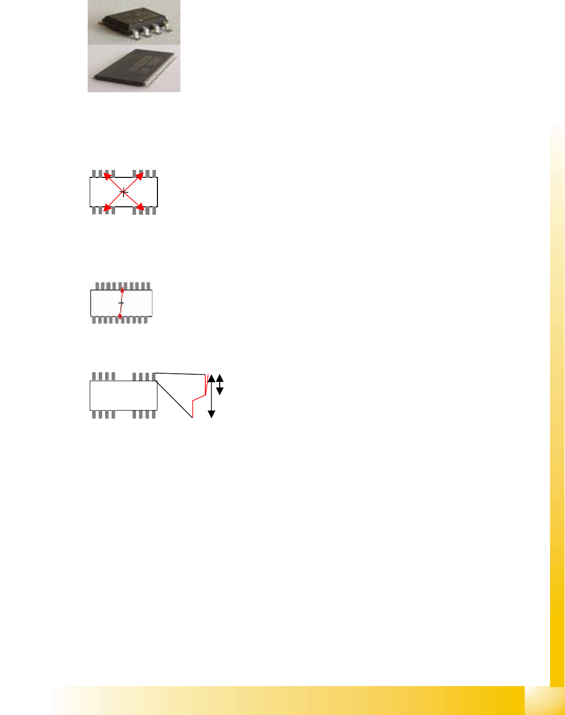
5.3.7.5 SOxx Component Shape (Small Outline xx)
JEDEC description
Group description
Lead description
Special features
SOxx with J-BEND type leads are classified as SOJ.
SOxx contain DIP, SSOP, SOP and TSOP.
Inspection of the lead number, position and pitch is set as a default for these leads and therefore can
not be disabled.
COPLANARITY measurement is possible provided the option has been installed.
Joint datasets with ICOS data possible –
SW extensions: FaceDown recognition (See: New Siplace Vision Functions 702).can be programmed
and from SC 702.01 SW (SIPLACE Vision 4.1).
(see MS-012 and MS-027)
Body description: rectangular.
The Z height of the body determines the CO height for the
Z positioning profile.
The X/Y body dimensions determine the field of vision, the
Region of Interest.
This also determines the inner starting edge of the Gullwing
leads.
This component shape has two (or more) lead groups on
two component sides, meaning that the CO must be
asymmetrical to one of the body axes.
The leads in the two groups must be identical!
The lead pitch and pitch tolerance must be identical in all
groups.
Different numbers of leads are permitted.
An offset between the two groups opposite one another is
also permitted.
This component shape has Gullwing leads i.e. the leads
protrude upwards from the IC level and point outwards in
the shape of a fan.
These leads are as wide as the solder resist contact
surface, on the board connection surface.
The lead length is significantly longer than the contact
length.
The leads are outside the body surface. Notches may not
be programmed.
Component Shapes
Specific Component Shapes Leaded Component Shapes
Student Guide SIPLACE Vision (Customer)
Component Shapes Edition 12/2008 EN
76
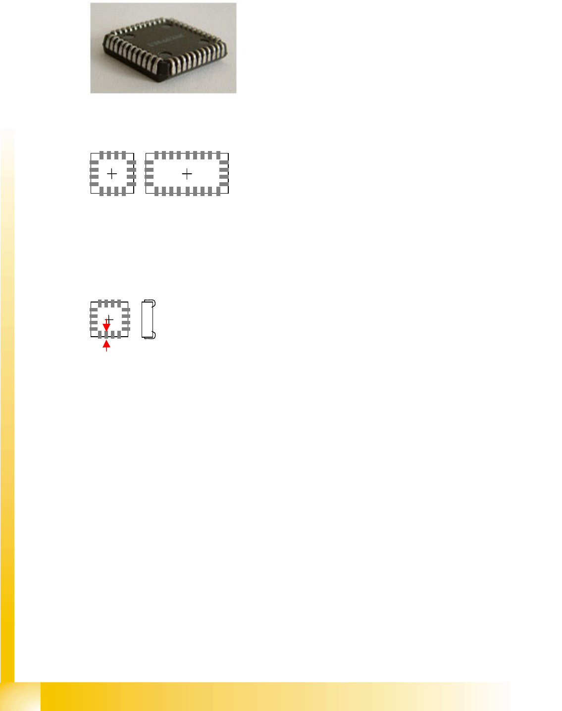
5.3.7.6 PLCC Component Shape (Plastic Leaded Chip Carrier)
JEDEC description
Group description
Lead description
Special features
Inspection mode is set as a default for these leads and can not be disabled.
The illumination is set to J-Lead classification.
We do not recommend selecting the COPLANARITY measurement option for this component
shape, since the hemispherical connection surfaces prevent reliable measurement results.
J-Leads should only be programmed when the component shape is really a J-Lead, otherwise
recognition errors could occur.
Joint datasets with ICOS data possible -
Body description: rectangular or, in the most common special
case, square.
The Z height of the body determines the CO height for the
Z positioning profile.
The X/Y body dimensions determine the field of vision, the
Region of Interest.
The overall body outline is determined by the J-Lead leads.
This component shape has four lead groups on the four
component sides, meaning that the CO must be
symmetrical to the body axes.
The leads in the groups must be identical!
The (pitch) and pitch tolerance must be identical in all
groups.
The number of leads in the groups may differ!
This component shape has so-called J–Leads, i.e..leads
curved in the shape of a J.
The leads are arranged on one level, parallel to the surface
covered by the component and are curved under the
component body, in the shape of a J.
The leads are as long as the contact length.
The leads are inside the body surface. Notches may not be
programmed. The leads are aligned towards the body
center.