SIPLACE Vision Customer_en.pdf - 第96页
Component Shapes Specific Component Shapes Optical Recognition of Shields S tudent Guide SIPLACE V ision (Customer) Component Shapes Edition 12/2008 EN 96 Features found The example shown uses the pr ogramming option for…
Component Shapes
Optical Recognition of Shields Specific Component Shapes
Student Guide SIPLACE Vision (Customer)
Edition 12/2008 EN Component Shapes
95
5.3.12 Optical Recognition of Shields
The shield centering procedure determines the CO center position, based on corner recognition data.
A.) Coarse and
B.) Fine centering.
If no circles or similar are programmed, further component inspections will not be performed.
Coarse centering outer corner
As can be seen in the camera gray image, the
system searches for the brighter edge, from
outside.
Taken from below, these camera images usually
have a double edge at the outer corners. The
vertical sheet trim (arrow) forms the body height
and can be clearly recognized on both sides of the
corner, due to the corner recesses in the shield
cover.
On the horizontal side of the corner, the double
edge only covers 1.4 mm.
The defined image pairs are used to determine the
dark background (blue cross) and the
lighter CO body (blue ring).
Coarse centering inner corner
This double inner corner with corner protrusion
and slant will not be programmed, as the leg
lengths are too short. We recommend that you
create the distance between corners 2 mm greater
than the corner protrusion.
The vertical recognition line is set to the shortest
possible length of 1.8 mm (six image pairs with
minimum pitch).
Component Shapes
Specific Component Shapes Optical Recognition of Shields
Student Guide SIPLACE Vision (Customer)
Component Shapes Edition 12/2008 EN
96
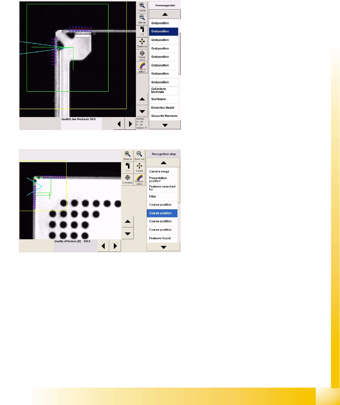
Features found
The example shown uses the programming option
for all four outer and all four inner corners.
The purple lines show the corner recognition
vectors.
The purple point is the corner inner point.
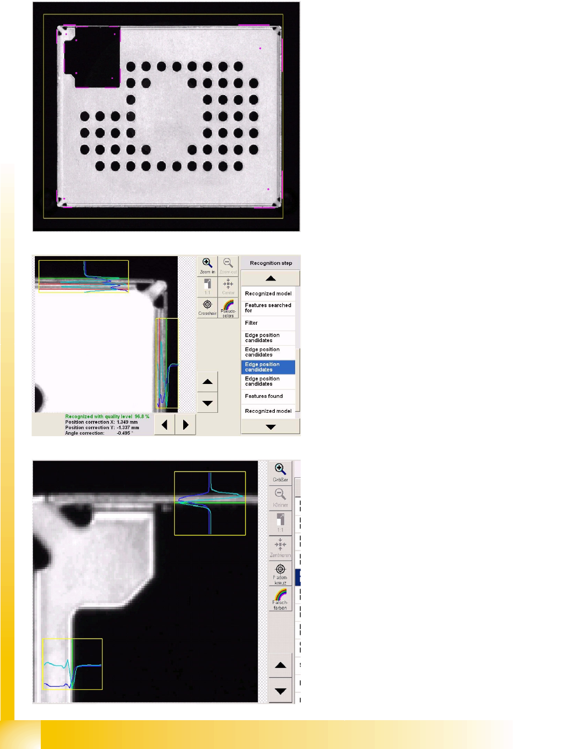
The step Recognized model also shows all
corners (shown in green here) and the coarse
position found.
Recognition step Edge position
candidates for outer edges
This steps uses brightness gradients to filter out
the real "edge to corner" distance at each corner
and on each of the two recognition edges.
The brightness in the vertical direction is shown in
dark blue here.
The brightness gradient for the evaluation is
turquoise/light blue.
The red lines show invalid edge positions, which
will not be considered as shield edges.
The green lines are valid edge positions.
Recognition step Edge position
candidates for inner edges
As inner edges are usually cut-outs, there is a
clear brightness transition here, which is
recognized as a shield edge.
In the top evaluation window, the evaluation can
be clearly seen on the vertical metal edge.
Component Shapes
Components with Open Descriptions Specific Component Shapes
Student Guide SIPLACE Vision (Customer)
Edition 12/2008 EN Component Shapes
97
5.3.13 Components with Open Descriptions
The optical features of shapes for some electrical components need to be programmed with individual
combinations or groups descriptions.
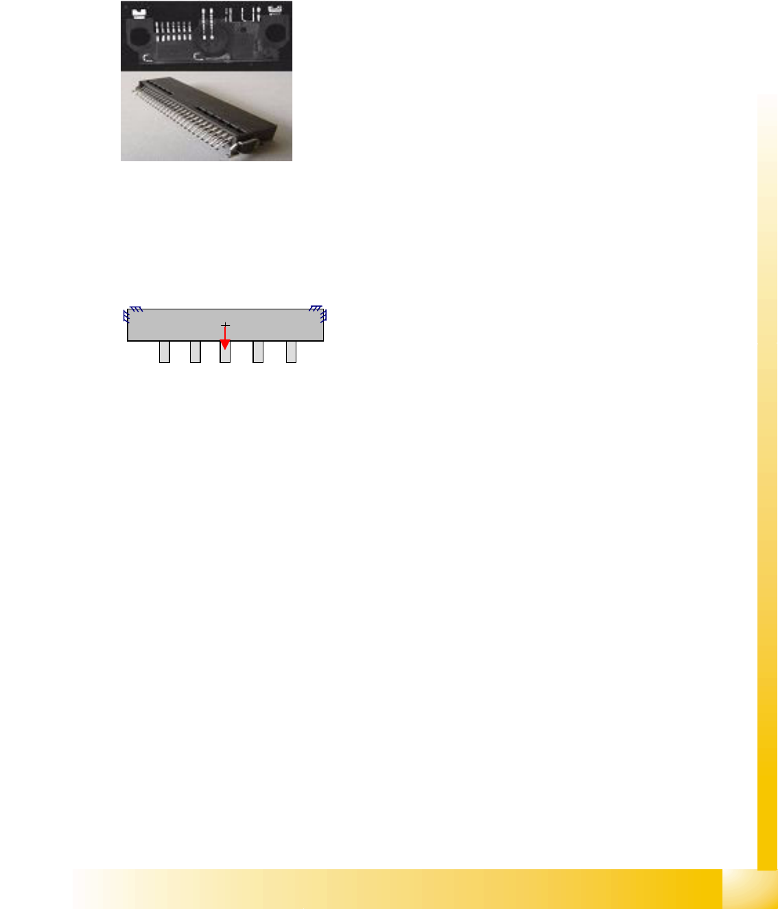
5.3.13.1 Connector Component Shape
JEDEC description
Group description
This component shape can have one or more lead groups on the component sides.
Different numbers of leads are permitted.
Lead description
Special features
Lead inspection can be selected in the geometry data menu.
COPLANARITY measurement is possible, if the option has been installed and the connector has
more than one lead row on different sides of the body.
SW extensions: FaceDown recognition (See: New Siplace Vision Functions 702).can be programmed
and from SC 702.01 SW (SIPLACE Vision 4.1).
Joint datasets with ICOS data possible –
Applicable if only Gullwing descriptions are used. ICOS can recognize leads with bright body edges in
white, red, orange and yellow bodies. It may be helpful to separate the datasets in this case.
Joint datasets with ICOS data NOT possible –
Applicable if SIPLACE Vision uses one of its own special recognition procedures (e.g. for corners or
special lead shapes).
Body description: could be irregular.
The Z-height of the body determines the CO height for the
Z positioning profile and the Z-position for centering with the
stationary camera.
The X/Y body dimensions determine the field of vision, the
Region of Interest.
This shape permits all lead shapes, including blob and -
from 702 SW - rectangle.
The leads are inside or outside the body surface and may
have notches.
Most single-row leads require correct geometry
descriptions of the lead and body.
To ensure correct measurement of single-row COs, it may
be helpful to program additional corners.
Attention: Shiny plastic could give recognition problems.