SIPLACE Vision Customer_en.pdf - 第72页
Component Shapes Specific Component Shapes Leaded Component Shapes S tudent Guide SIPLACE V ision (Customer) Component Shapes Edition 12/2008 EN 72 As you can see on the white dotted line , the body center i s higher. Fi…
Component Shapes
Leaded Component Shapes Specific Component Shapes
Student Guide SIPLACE Vision (Customer)
Edition 12/2008 EN Component Shapes
71
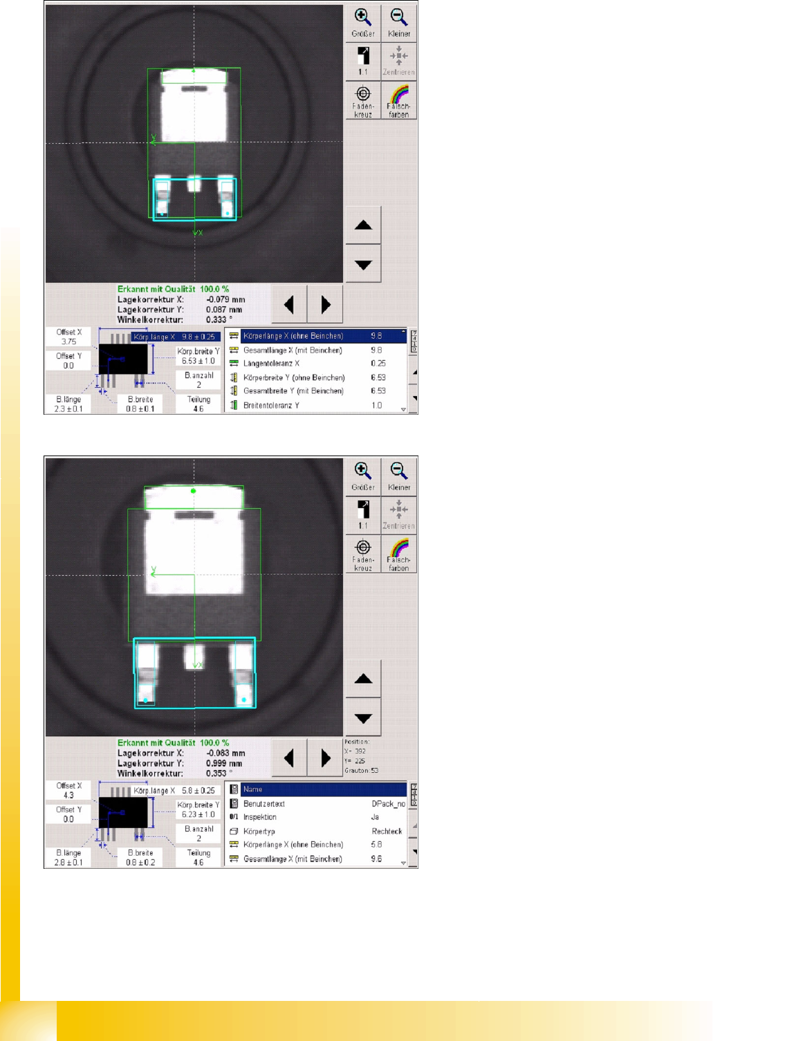
Several description options have been selected for ICOS:
LCU/LRL/ SIPLACE Pro 1.4: the CO center for placement forms the CO center for the overall
dimensions.
SIPLACE Pro 2.0: the CO center for placement forms the body center!
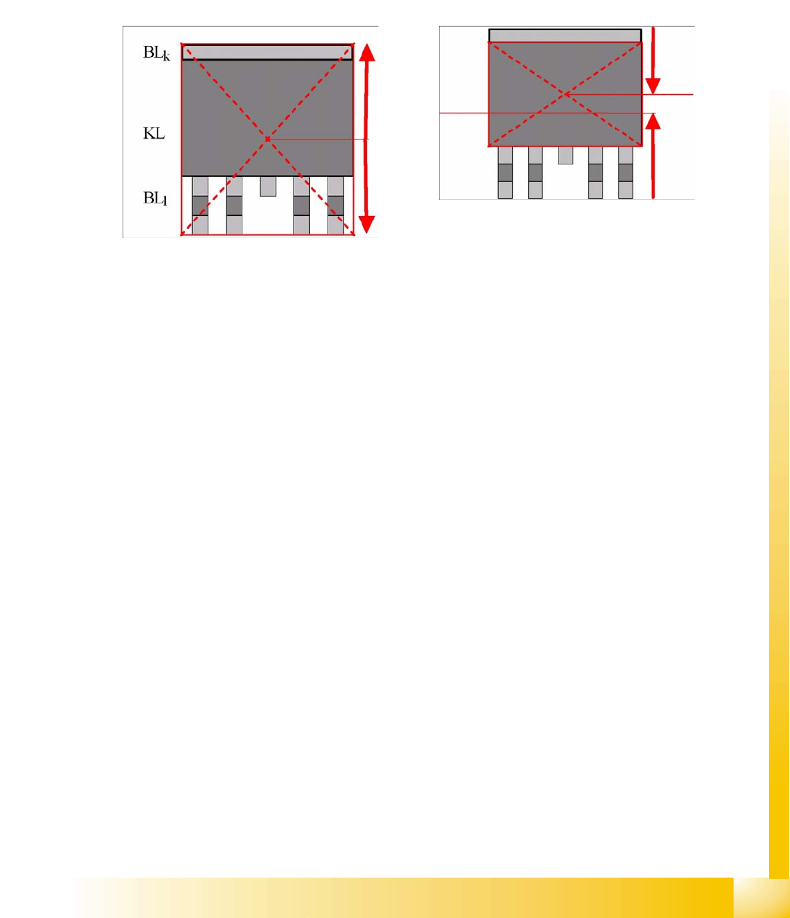
Explanations about Component Center and Body Center
The placement positions for DPACKs, as created by the CAD data, often refer to the center of the CO,
including leads.
Using the body center set in SIPLACE Pro (and the previous programming systems) as the reference
point has the advantage that you are not dependent on differing lead lengths and can always place the
nozzle on the level body center.
This necessitates adjustment of the placement position as follows:
Center displacement = lead length long – lead length short : 2
(If you should make the setting as follows
Lead length short = 1 mm / lead length long = 2 mm and body width = 6 mm
, you will recognize the CO center up to 4.5 mm from above / the body center will be at 4 mm from above.)
The CO center or body center, as determined during centering, needs to be matched with the board X/
Y placement position by the placement machine.
Component Shapes
Specific Component Shapes Leaded Component Shapes
Student Guide SIPLACE Vision (Customer)
Component Shapes Edition 12/2008 EN
72
As you can see on the white dotted line, the body center is higher.
Fig. Component center including leads
5-1: Body center without leads
Component Shapes
Leaded Component Shapes Specific Component Shapes
Student Guide SIPLACE Vision (Customer)
Edition 12/2008 EN Component Shapes
73
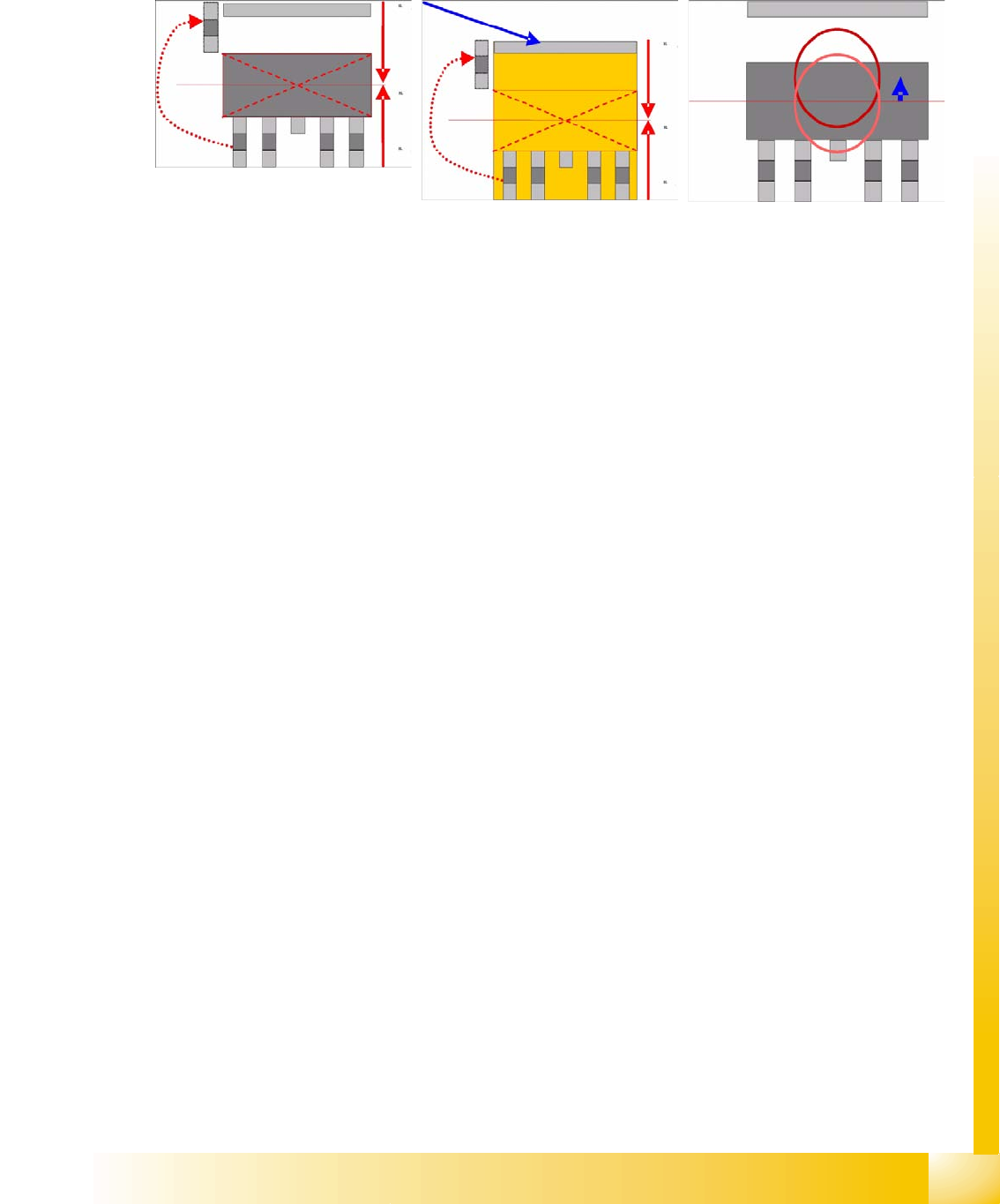
Use the following programming trick to avoid having to adjust the placement position:
When describing the body on the side of the short lead, shorten the length of the lead by the additional
length of the lead opposite. In the placement image printout, this gives the impression of a floating lead.
Alternatively, describe the body so that it includes the leads. SIPLACE Vision will not check this method
of programming.
To solve the problem and achieve satisfactory nozzle contact, you can also set a pickup offset in the CS.
These asymmetrical lead arrangements also apply to other CS types.
Joint datasets with ICOS data NOT possible: If ICOS descriptions do not include a heat sink (tab) lead
definition. There are some descriptions in which the body size is programmed incorrectly to simulate
pickup and placement symmetrical to the center point.
SW extensions: FaceDown recognition (See: New Siplace Vision Functions 702).can be programmed
and from SC 702.01 SW (SIPLACE Vision 4.1).