SIPLACE Vision Customer_en.pdf - 第34页
User Interface Error Analysis Logs Paths and Settings S tudent Guide SIPLACE V ision (Customer) User Interface Edition 12/2008 EN 34 4.10.2 Paths and Settings Log folder The measurement context files are stored in th e f…
User Interface
Enabling Vision Log Recording Error Analysis Logs
Student Guide SIPLACE Vision (Customer)
Edition 12/2008 EN User Interface
33
4.10.1.2 Vision Measurement
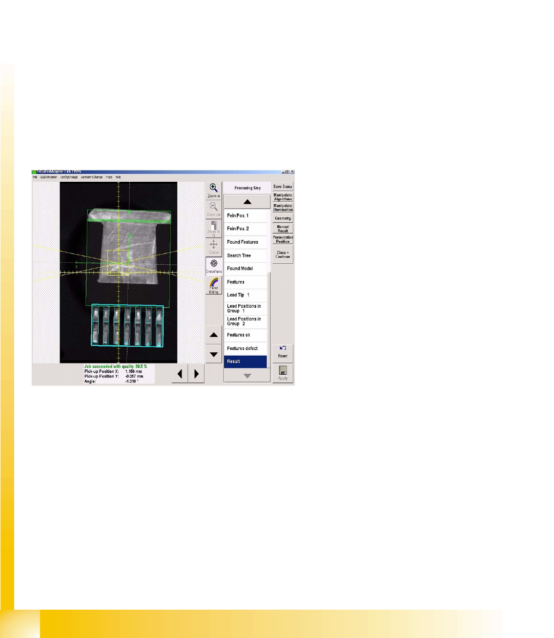
The individual steps and corresponding results for the optical centering recorded in this error example
can be examined analogous to the analysis surface.
The presentation in the pseudo-colors figure shows the areas of contrast on the component.
The crosshairs show the component pickup offset. Use the zoom function to view details. Each
measurement step and the corresponding result can be viewed in detail in the recognition step menu.
See also:
J
4.10.1.1 Vision Measurement Options [
J
32]
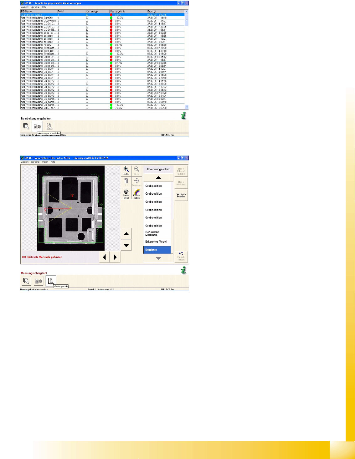
The measurement log shown here is issued when
enabled in Measurement options and can be
called up at Vision measurements, when an error
occurs.
In the menu Display Measurement the individual
measurement steps are shown for the selected
components.
The analysis log in this example shows incorrect
programming of the vectors for corner recognition:
the system tries to locate the light-colored Shield
surfaces to the left of the respective corner
recognition vector.
User Interface
Error Analysis Logs Paths and Settings
Student Guide SIPLACE Vision (Customer)
User Interface Edition 12/2008 EN
34
4.10.2 Paths and Settings
Log folder
The measurement context files are stored in the following folder (for the 6xx SW) on the SC C drive:
C:\Documents and Settings\Operator\Local Settings\Temp\SV Dumps
When using 7xx SW, the following 3 folders are taken: Other dump for machine check / Part dumps for
CSs and PCD dumps for fiducials in C:\SIRIO\Work\SVDumps\
Since SR/MC 603, all selected measurement log files can be saved to any external data carriers from
the menu window, with the
Save As …
command.
Log name
The file names for these recordings are automatically assigned as follows:
Sensor 1033_9-21-02 AM,4.svdmp
If analysis/result log recording is enabled on the Vision interface via Save Dump, the naming schema is
as follows:
PCB-name_CO-name, 9-21-02 AM,4.svdmp
If CO image recording is enabled on the Vision programming interface, the naming schema is as
specified above:
If these log files are opened with the SIPLACE SR
interface CS test menu, the optical centering
results will be displayed, step for step.

User Interface
Creating Component Shapes Component Shape Wizard
Student Guide SIPLACE Vision (Customer)
Edition 12/2008 EN User Interface
35
4.11 Component Shape Wizard
From SW version 603.01, the Component Shape Editor in SIPLACE Pro features a component shape
creation feature at the station, for teaching component shapes.
This is a camera-supported, semi-automatic function for creation of component shapes (CS), which still
allows the programmer to make the final decision about values which influence quality.
4.11.1 Creating Component Shapes
To create component shapes (CS), there is a manual programming function with camera support at the
station and a CS wizard tool. This CS wizard does not provide all possible CS types but only supports
the following selection for complex lead arrangements:
ECV
SOXX, SOT, DPACK, QFP
SOJ, PLCC
BGA/FlipChip, CCGA
Shield
Socket, connector, nonstandard
Further CS-types have to be programmed manually.Simple rules, which are allocated to the component
shape, are used to reduce programming to a minimum.
BareDies consist only of the body dimensions, which can be programmed with length and width (plus
the corresponding tolerances). (The Z height can only be changed in SIPLACE Pro.)
CHIP and MELF consist only of bodies with attached wraparound leads. Once the body length and width
and the lead length (and tolerance) are defined, everything has been programmed. (The leads are as
wide as the body. The offset of the lead groups is calculated from the body length and lead length).
When using shapes of the type "molded", the lead width also needs to be programmed, in addition to the
dimensions required for CHIP types. This is because the leads are narrower than the body width.
The programming process with the CS wizard ALWAYS involves AN image recording. Teaching with the
CS wizard can therefore NOT be interrupted or continued for adding further lead features to existing
programming.
At the end of programming or teaching with the wizard, each CS needs to be centered multiple times.
The aim is to test whether the X/Y and angular values are found to be stabile. This test should be
performed at different angles and in various positions, to make sure that subsequent placement does
not randomly fail at different positions. An even better method is to perform optical recognition with
various different components.
It may be helpful to run a robustness test, which is integrated from station SW 605.01 or from teach
station SW 604.01 for SIPLACE Vision.
The following diagram shows an easy procedure in order get a good illumination also in case of difficult
CS.