SIPLACE Vision Customer_en.pdf - 第79页
Component Shapes Optical Recognition and Evaluation of Leaded COs Specific Component Shapes S tudent Guide SIPLACE Vision (Customer) Edition 12/2008 EN Component Shapes 79 5.3.8 Optical Recognition an d Evaluation of Lea…
Component Shapes
Specific Component Shapes Leaded Component Shapes
Student Guide SIPLACE Vision (Customer)
Component Shapes Edition 12/2008 EN
78
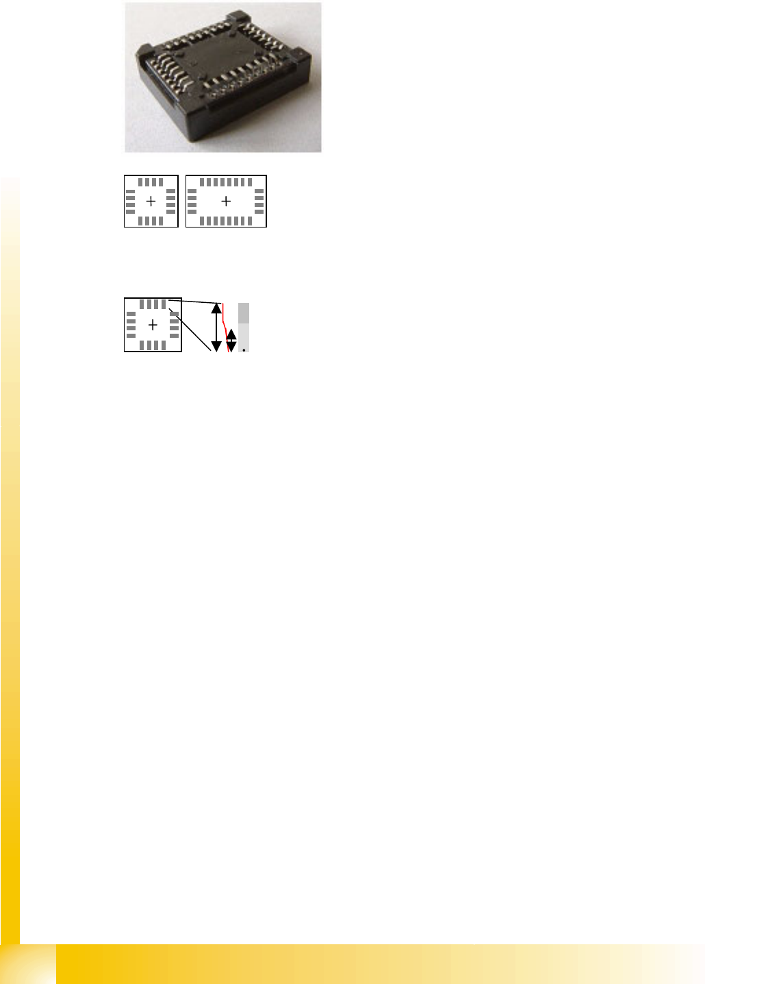
5.3.7.8 Socket Component Shape
JEDEC description
Group description
Lead description
All lead types are permitted for this component shape.
The leads are inside the body surface. Notches can not be programmed.
Socket with a 90° lead alignment (pointing outwards) could also be recognized as QFP.
Special features
Inspection of the lead number, position and pitch is currently not available and can therefore not be
enabled.
In many cases, the socket has leads which have half the width of the contact in the socket frame. In
this case, only the width of the socket frame (visible metal surface) is programmed.
Theoretically, a round Socket could also be programmed.
Joint datasets with ICOS data possible –
SW extensions: FaceDown recognition (See: New Siplace Vision Functions 702).can be programmed
and from SC 702.01 SW (SIPLACE Vision 4.1).
Body description: rectangular.
The Z height of the body is the height in the CO center.
The X/Y body dimensions determine the field of vision, the
Region of Interest.
Here: View from below
One or more groups are permitted.
The leads in the groups must be identical!
The (pitch) and pitch tolerance must be identical in all
groups.
Different numbers of leads are permitted.
The lead groups may be aligned inwards or outwards.
Component Shapes
Optical Recognition and Evaluation of Leaded COs Specific Component Shapes
Student Guide SIPLACE Vision (Customer)
Edition 12/2008 EN Component Shapes
79
5.3.8 Optical Recognition and Evaluation of Leaded COs
Shown in the example of a SO 14…
A leaded CO is processed with the following measurement steps:
1. Position recognition through:
A.) Recognition of possible feature positions
B.) Filtering, evaluation and determination of actual features
C.) Combination of features so that the CO center position can be calculated for placement.
2. Component inspection via:
A.) Determination of feature position
B.) Determination of feature quality
C.) Recalculation of CO position.
The term "feature" stands for programmed, recognizable parts of the component, suitable for clear
determination of the CO center for placement purposes.
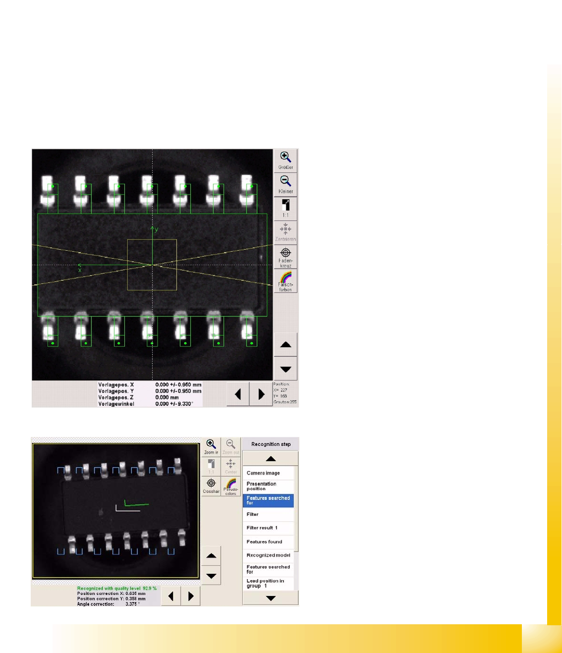
5.3.8.1 Determination of Leaded CO Position
Diagram Presentation position
This menu is the same as that used for the
unleaded COs.
The green points in the leads indicate the lead
ends.
Attention: an incorrect lead angle will result in false
measurement values!
The division in the leads shows the contact length
(at the end of the pin) for a Gullwing lead type.
The outline of the plastic body should reach up to
where the lead begins, making evaluation and
correct programming simpler. SIPLACE Vision will
not check this dimension.
The gray value of 255 in the diagram on the left,
shows that the mouse cursor is pointing to a part
of the camera field which has this brightness.
The gray value 255 means that the mouse cursor
has been placed on a bright contact surface.
Presentation Features searched for
The blue U-shaped tick marks the gullwing lead
ends searched for i.e. the contact surfaces.
The green tick shows the measured CO center
(also see the measurement results below the
screenshot).
The white tick shows the expected CO center in
the CO camera center.
Component Shapes
Specific Component Shapes Optical Recognition and Evaluation of Leaded COs
Student Guide SIPLACE Vision (Customer)
Component Shapes Edition 12/2008 EN
80
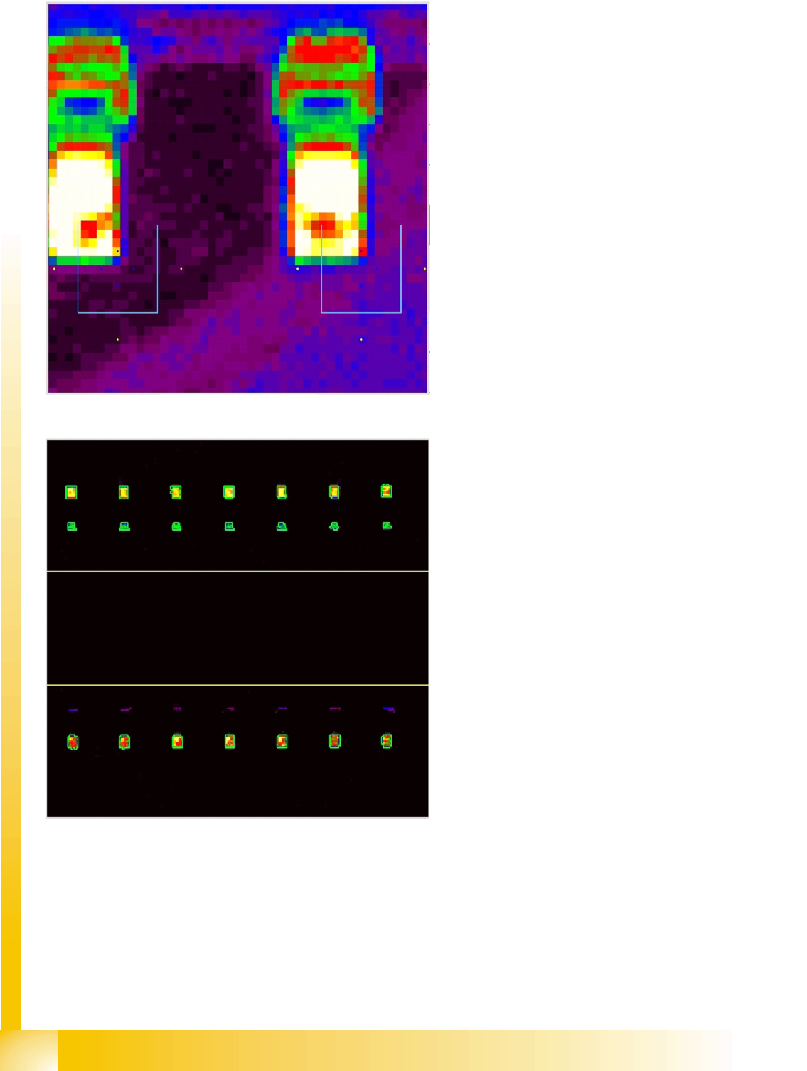
Presentation of lead filters
In the diagram, the evaluation points for
recognition of the gullwing contact surfaces are
marked at the expected lead positions.
Dark blue shows the four evaluation points for the
bright contact surface.
Yellow shows the three evaluation points for the
dark background.
Red and green shows the lead background and
the lead bend.
The contact surface is shown by: white/yellow
with a red/green outline.
Recognition step Filter result 1
The lead brightness is recognized by the filtering
process. The appropriate regions are outlined in
green (including the lead surfaces in the
background), indicating that they have been
recognized as lead candidates.
Increased illumination helps the system to
recognize the lead parts in the background row
below. This menu clearly demonstrates the effect
achieved by changing the illumination.