JAKA Zu se使用手册 - 英文版.pdf - 第15页
JAKA Zu Se 15 Sensor Size a. Before inst allation, please check that there is no damage or foreign m atter on the surface of installation equipment, adaptor pl ate and sensor. If the contact is not uniform due to foreign…
14 JAKA Zu Se
Chapter 6 Appendix
6.1 Description of sensor I
1.1 Overview
This strain type six-axis force/torque sensor can detect three forces and three torques
simultaneously. The sensor detects the relative deformation between the "Tool Side Flange" and the
"Body" caused by the applied force, and uses a resistance strain gauge to measure changes in the
sensor's elastic unit. The sensor contains an embedded system, which can collect and process the
signal changes of the resistance strain gauge in real time, and output the magnitude and direction of
the applied force in real time, with high precision and high response capability. When using the
sensor, please install it correctly avoid interference with the output result.
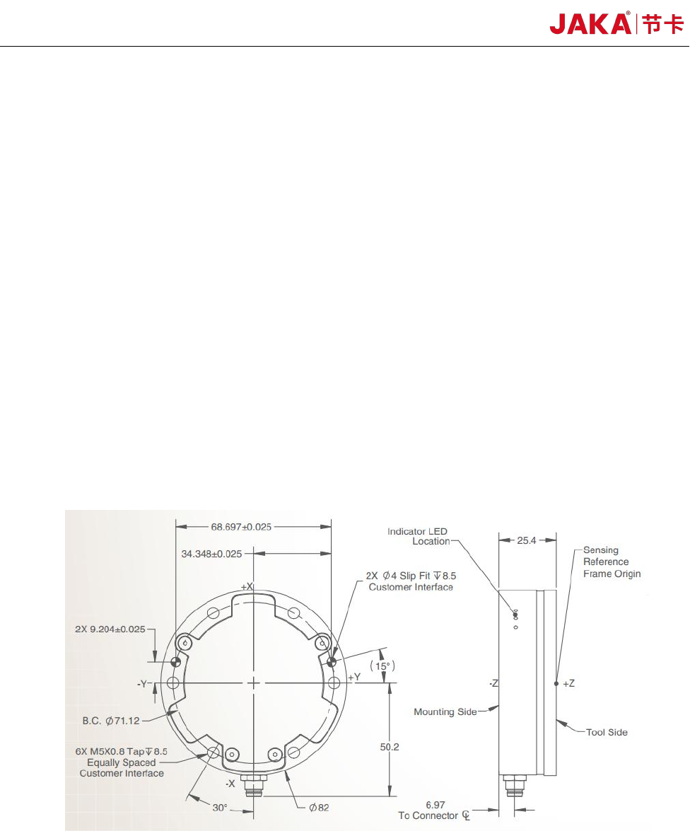
1.2 Sensor Installation
The sensor mounting hole position and mounting dimensions are as follows.
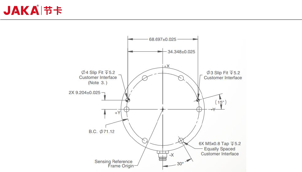
JAKA Zu Se 15
Sensor Size
a. Before installation, please check that there is no damage or foreign matter on the surface of
installation equipment, adaptor plate and sensor. If the contact is not uniform due to foreign matters
and other factors, a gap will be formed between the equipment (or adaptor board) to be installed,
which cannot guarantee the IP64 performance of the product and will impact the output effect of the
actual sensor.
b. Separate the sensor from the adaptor plate and install the adaptor plate on the robot side
flange. It is important to note that before the installation of the sensor, the X and Y directions of the
sensor coordinate system shall be guaranteed to be consistent with the X and Y directions of the
robot side flange coordinate system through pre-installation, that is, the TIO direction of the robot
side flange center shall be consistent with the -Y direction of the sensor. If the installation direction
is inconsistent, it will affect the subsequent use.
c. Tighten the connection between the sensor and the adaptor plate. 6 M5 hexangular set bolts
shall be gradually tightened diagonally to make uniform contact between the sensor and the adapter
plate.
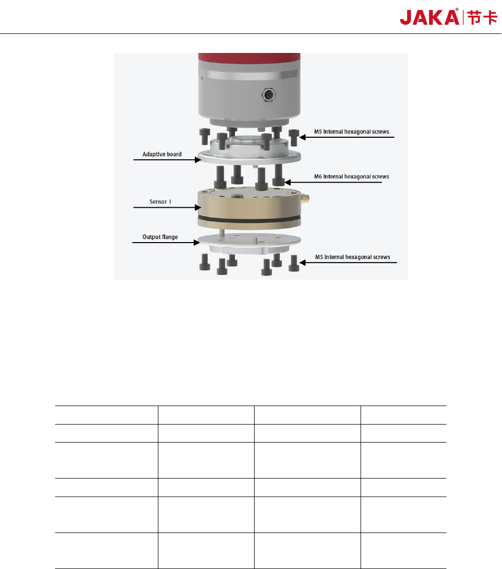
16 JAKA Zu Se
Schematic Diagram of Connection and Installation of the Sensor and Equipment
d. Connect the output flange to the output side of the sensor. The mechanical interface of the
output flange shall be the same as that of the robot side flange.
1.3 Basic Sensor Parameters
Fx/Fy(N)
200
Fz(N)
360
Mx/My(Nm)
8
Mz(Nm)
8
Overload level
(%)
500
Accuracy (%)
0.5
Precision (%)
0.1
Protective class
IP64
Operating
temperature (°C)
5~80
Power supply
voltage (V)
12~24
Communication
Interface
Ethernet
System
Resolution (Bit)
16
Precision: Precision is the evaluation index symbolizing the extent of consistency between
multiple measured values, that is, the output curve consistency degree obtained by the sensor when
the input is tested for multiple times in a unified direction. The precision of reproducibility is the
percentage of the standard deviation of the output error to the rated output (%FS).
Accuracy: Accuracy is the evaluation index of the deviation degree between the measured value
and the true value. Accuracy refers to the percentage of the standard deviation of the deviation
between the output and the theoretical truth value and the rated output (%FS).