JAKA Zu se使用手册 - 英文版.pdf - 第8页
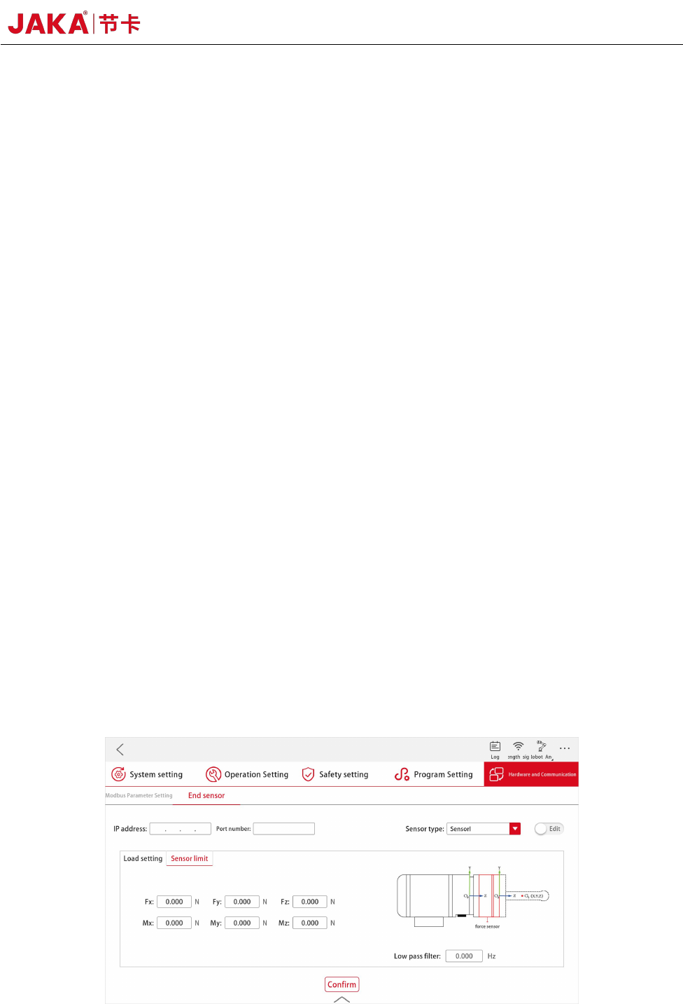
8 JAKA Zu Se c. Tract ion teaching function As shown in Figure 3, after selecting t he sensor t ype and setting IP, port number, filtering and load, etc., the controller starts to receive data from the sensor after press…
JAKA Zu Se 7
Chapter 4 Use of JAKA Zu se
a. Automatic load identification function
When the force control function is used, accurate load parameters shall be set first. Manual
input can be selected in [Load Settings]; the automatic identification function can also be used. The
process is as follows:
[Set the Starting Position] Enter the manual interface, move the robot to the appropriate position,
and confirm to exit;
[Set the End Position] Enter the manual interface, and only joints 4, 5 and 6 are allowed to
move, with the motion range within ±90° of the initial position (under the condition that the robot's
motion is not interfered, the larger the motion range is, the more accurate the identification result will
be), and confirm to exit;
[Pilot Operation], long press [Set the Starting Position] to return to the initial position, long
press [Pilot Operation] to confirm that there is no interference in the identified track;
[Start Identification], long press [Set the Starting Position] to return to the initial position, click
[Start Identification], wait for a few seconds, the APP will display the identification results, the
results are correct and confirmed; If there are problems, they can be identified again.
b. Security protection function
The safety force value is set in [Sensor Limit]. During the movement of the robot, if the force at
the end of the sensor is greater than the set threshold, the robot will stop its movement immediately
to avoid causing danger or property loss.
Figure 4. Settings of JAKA Zu Se Security Protection Function

8 JAKA Zu Se
c. Traction teaching function
As shown in Figure 3, after selecting the sensor type and setting IP, port number, filtering and
load, etc., the controller starts to receive data from the sensor after pressing [OK] and [Run].
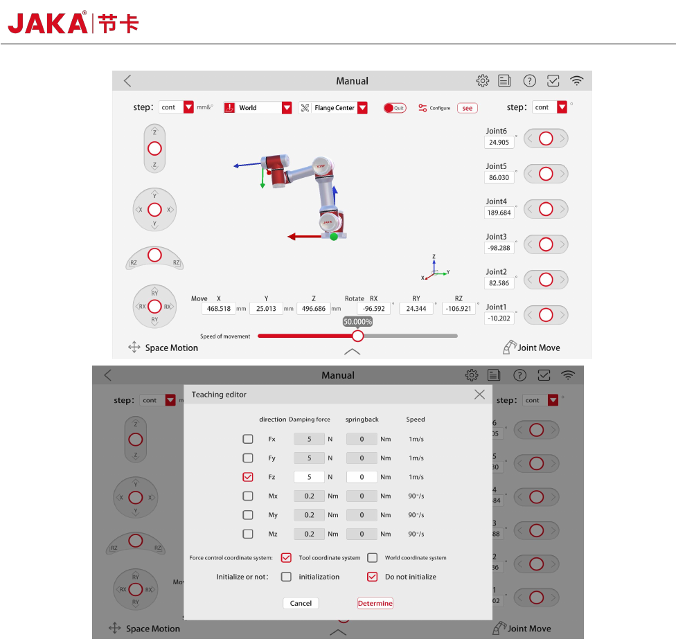
As shown in Figure 4, enter [Manual operation]. First, enter [Configuration] interface, where Fx,
Fy and Fz correspond to displacement in X, Y and Z directions, and Mx, My and Mz correspond to
rotation in X, Y and Z directions. By checking the □ in front of [Direction] to enable a certain
direction or several directions, that is, after the drag and drop is opened, the robot can be dragged in
the enabling direction. The smaller the setting of [Damping force] is, the smaller the drag force is
required by the user. However, the smaller setting of [Damping force] is not the better. It is
suggested that F is greater than 10N and M is greater than 0.2nm, and the setting value shall not be 0.
[Rebound] enables the robot to return to the original position before dragging. The larger the setting
value is, the greater the force is required to drag the robot;
Tick "Tool Coordinate System" to drag the robot in the set tool coordinate system. Tick [World
Coordinate System], then drag the robot in the base coordinate system;
Initialize or not. After the controller runs, it enters the drag mode for the first time. tick
[Initialize] to compensate the sensor bias and load, and ensure that there is no external force contact
at the end of the robot during the drag, otherwise the compensation accuracy will be affected.
After the parameters are configured, click [OK] and then click [Exit] to enter the [Drag] mode.
Before entering the drag mode, the robot end shall not be subjected to external force, otherwise it
will cause compensation error of the sensor and cause danger.
Due to the temperature drift and other reasons of the sensor, if the robot's position drifts in the
drag mode, please [Exit] and enter [Drag] to make sensor compensation again. Do not use traction
teaching function, please [Exit] in time.
JAKA Zu Se 9
Figure 5. Settings of JAKA Zu Se Traction Teaching Function
d. Constant force model
Constant force mode ensures that the contact force between the robot end and the external
environment is within the range of the set constant force value. As shown in Figure 5, the constant
force mode includes [Open the Constant Force Compliance Control], [Setting the Force Control
Coordinate System], Setting the Constant Force Compliance Parameter] and [Close the Constant
Force Compliance Control]. On the interface of [Constant force compliance parameter setting], the
configuration parameters are consistent with the traction teaching parameters. Users can set the value
of [Constant Force] according to the desired contact force value. The size of [Damping Force] needs
to match the external environmental stiffness. Generally speaking, the greater the environmental
stiffness is, the greater the value of [Damping Force] is required. Due to the temperature drift of the