JAKA Zu se使用手册 - 英文版.pdf - 第21页
JAKA Zu Se 21 Loosen the em bedded s crew with 3mm inner hex agon wr ench c . Ti ghten the connection between the sensor and the adaptor plate. The alignment pin is used to coordinate the sensor with the adaptor plate to…
20 JAKA Zu Se
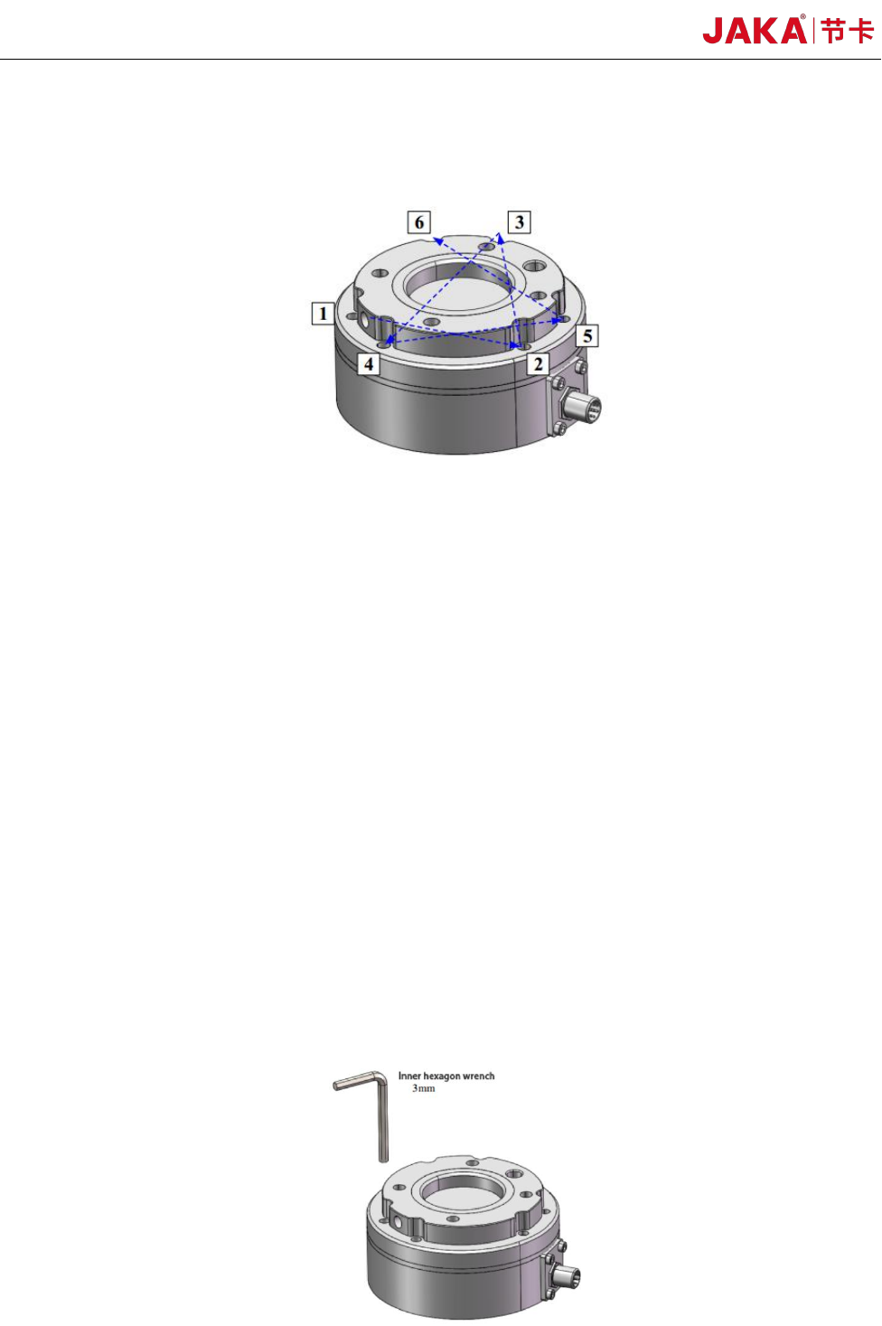
During tightening the bolts, please tighten the bolts gradually in the diagonal order as shown in
the figure to make uniform contact between the sensor and the equipment to be installed or the
transfer fixture.
Bolt Tightening Sequence
a. Before installation, please check that there is no damage or foreign matter on the surface of
installation equipment, adaptor plate and sensor. If the contact is not uniform due to foreign matters
and other factors, a gap will be formed between the equipment (or adaptor board) to be installed,
which cannot guarantee the IP64 performance of the product and will impact the output effect of the
actual sensor.
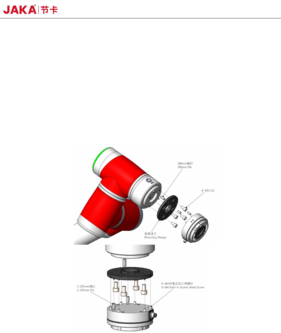
b. Separate the sensor from the adaptor plate and install the adaptor plate on the equipment to be
installed. When the sensor is delivered from the factory, the adaptor plate and the sensor body are
connected by 6 embedded hexangular bolts. Loosen 6 embedded hexagon socket bolts with 3mm
hexagon socket wrench and separate the adaptor plate from the sensor body. Use a φ6 alignment pin
to position the adaptor at the robotic arm end and the equipment to be installed. Use 2 M6 standard
hexagon socket bolts and 2 M6 non-standard hexagon socket bolts in the packaging accessories of
this product to fix the adaptor and the equipment to be installed. The alignment pin is used to obtain
repeatability of the equipment installation and connection. If the locating pin is not used, the sensor
performance will not be affected.
JAKA Zu Se 21
Loosen the embedded screw with 3mm inner hexagon wrench
c. Tighten the connection between the sensor and the adaptor plate. The alignment pin is used to
coordinate the sensor with the adaptor plate to ensure that the sensor is installed in the same direction
as the equipment. Tighten with the sensor's 6 embedded bolts. Insert the hexagon socket wrench
(3mm) from the mounting hole of the sensor tool side flange, and then rotate along the right screw to
fix it. Screw tightening shall be operated in the following sequence. In order to better guarantee the
IP64 protection level of the sensor, 6 M5 plug head screws can be screwed into 6 corresponding
threaded holes on the tool side flange after the sensor is installed, so as to ensure a certain degree of
isolation between the internal cavity of the sensor and the external environment.
Schematic Diagram of Connection and Installation of the Sensor and Equipment
d. Connect the tool interface of the equipment to the sensor tool side flange. The sensor tool side
flange provides 4 M6 bolt holes and φ6 pin hole form of general interface for the connection of
equipment and tools. The sensor tool side flange alignment pin is to obtain the repeatability of
equipment and tool installation. If the alignment pin is not used, the sensor performance will not be
affected.
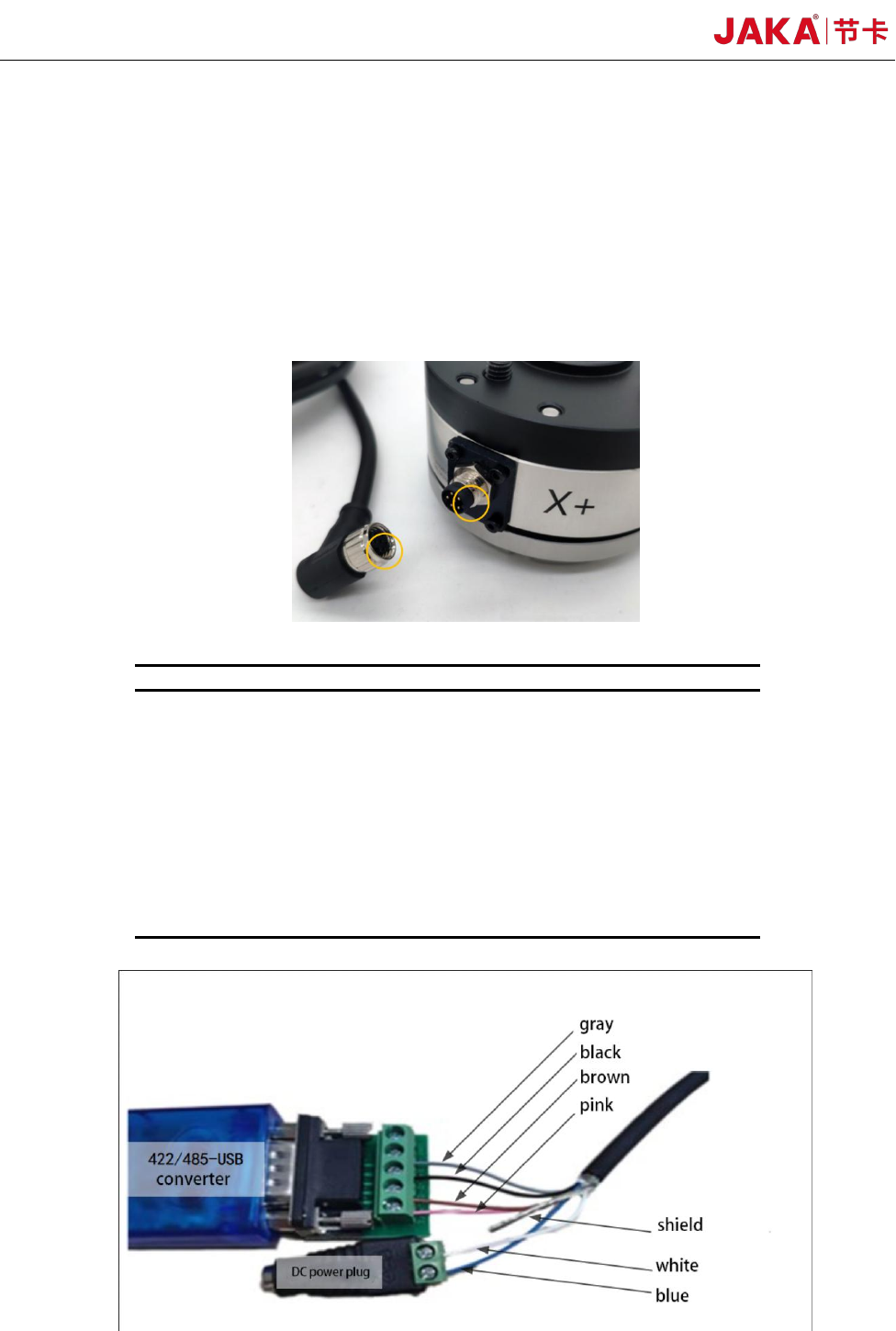
e. The connection cables are delivered with the product. The connection cable is a multi-core
22 JAKA Zu Se
cable with interfaces matching the cable interface on the sensor. Align and push the multi-core cable
interface with the sensor cable interface as shown below. After being pushed in, the threaded
connection shell from the multi-core cable interface shall be tightened to avoid looseness of the cable,
so as to achieve the performance of IP64. It shall be noted that during installation, the wiring of each
cable core is operated strictly according to the color definition of the given core. If the positive and
negative poles of the power supply are connected in reverse, the sensor will be damaged. Please be
careful!
Cable Connection Operation
No.
Core color
Definition
1
Blue
Power supply+
2
White
Power supply –
3
Powder
Bus 422 sensor receiving
terminal +
4
Brown
Bus 422 sensor receiving
terminal -
5
Black
422 or 485 bus sensor
sending terminal +
6
Gray
422 or 485 bus sensor
sending terminal -
7
Shield
422/485-USB Wiring Diagram of Converter and Power Plug