JAKA Zu se使用手册 - 英文版.pdf - 第6页
6 JAKA Zu Se Chapter 3 JAKA Zu Se System Constructi on As shown in Figure 2 and 3, users need to complete simple hardware connection and software settings t o rea lize t he setup of JAKA Zu se sy stem. The specific setup…
JAKA Zu Se 5
Chapter 2 Product Description
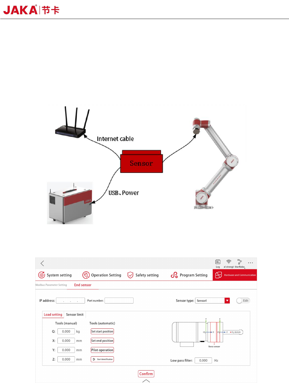
The JAKA Zu se system includes an APP, a robot, a control cabinet, and a force-sensing sensor
device. As shown in Figure 2, the force-sensing sensor and the robot end flange are mechanically
connected. The operation on the software is realized through the force sensor module in JAKA Zu
APP, as shown in Figure 3.
Figure 2 JAKA Zu Se System Diagram
Figure 3 APP Setting Interface of Force Sensor Module

6 JAKA Zu Se
Chapter 3 JAKA Zu Se System Construction
As shown in Figure 2 and 3, users need to complete simple hardware connection and software
settings to realize the setup of JAKA Zu se system. The specific setup process is as follows:
a. The user designs the connection between the force sensor and the end flange according to the
actual demand, and ensures that the X+ direction of the sensor is consistent with the X+ direction of
the robot flange through the connection or setting the tool coordinate system.
b. The force-sensing sensor can be powered by a robot controller or an additional 24V DC
power supply to the user. According to the different communication modes of the sensor, the sensor
can carry out serial communication through the USB interface connected to the control cabinet or
TCP communication through the network interface.
c. If sensor I or III is selected, IP and port number settings need to be made in the APP. Please
refer to the relevant sensor configuration appendix for specific setting methods. If sensor II is
selected, no IP and port number settings are required.
JAKA Zu Se 7
Chapter 4 Use of JAKA Zu se
a. Automatic load identification function
When the force control function is used, accurate load parameters shall be set first. Manual
input can be selected in [Load Settings]; the automatic identification function can also be used. The
process is as follows:
[Set the Starting Position] Enter the manual interface, move the robot to the appropriate position,
and confirm to exit;
[Set the End Position] Enter the manual interface, and only joints 4, 5 and 6 are allowed to
move, with the motion range within ±90° of the initial position (under the condition that the robot's
motion is not interfered, the larger the motion range is, the more accurate the identification result will
be), and confirm to exit;
[Pilot Operation], long press [Set the Starting Position] to return to the initial position, long
press [Pilot Operation] to confirm that there is no interference in the identified track;
[Start Identification], long press [Set the Starting Position] to return to the initial position, click
[Start Identification], wait for a few seconds, the APP will display the identification results, the
results are correct and confirmed; If there are problems, they can be identified again.
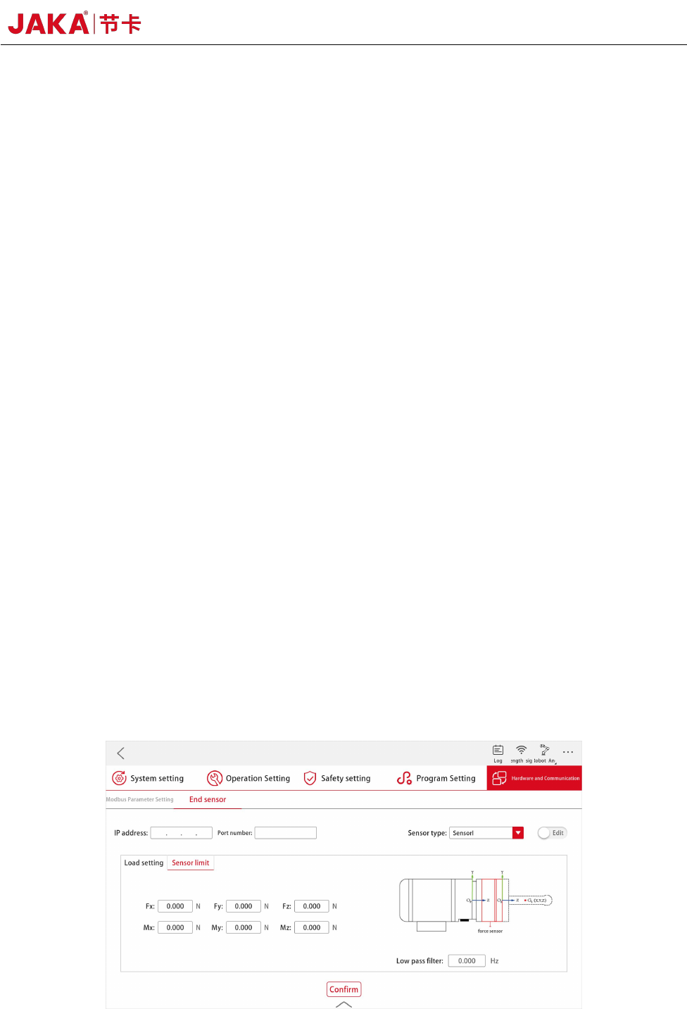
b. Security protection function
The safety force value is set in [Sensor Limit]. During the movement of the robot, if the force at
the end of the sensor is greater than the set threshold, the robot will stop its movement immediately
to avoid causing danger or property loss.
Figure 4. Settings of JAKA Zu Se Security Protection Function