JAKA Zu se使用手册 - 英文版.pdf - 第26页
26 JAK A Zu Se Sensor Instal lation To t ighten the s crews, pl ease tighten them gradually in the diagonal sequence. to m ake uniform contact between the sensor and the equipment to be i nstalled or t he transfer fixt u…
JAKA Zu Se 25
6.2 Description of Sensor III
1.1 Overview
This strain type six-axis force/torque sensor can detect three forces and three torques
simultaneously. Six-axial load sensors are generally divided into fixed side (robot side) and loading
side (tool side). When the two sides of the sensor are under relative force, elastic deformation occurs
and the resistance of the strain gauge inside the sensor changes, which is then converted into voltage
signal output.
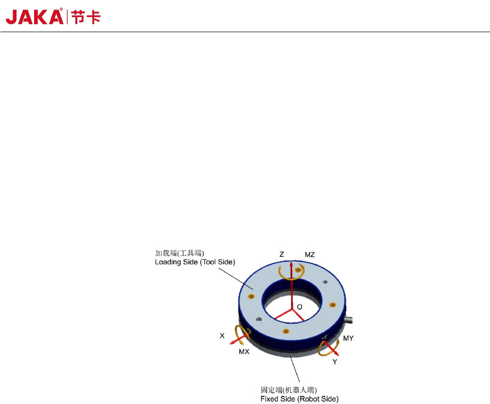
The output force and torque of the six-axis force sensor are relative to the neutral coordinate
system, which is generally located in the geometric center of the sensor.
Definition of the Sensor Coordinate System
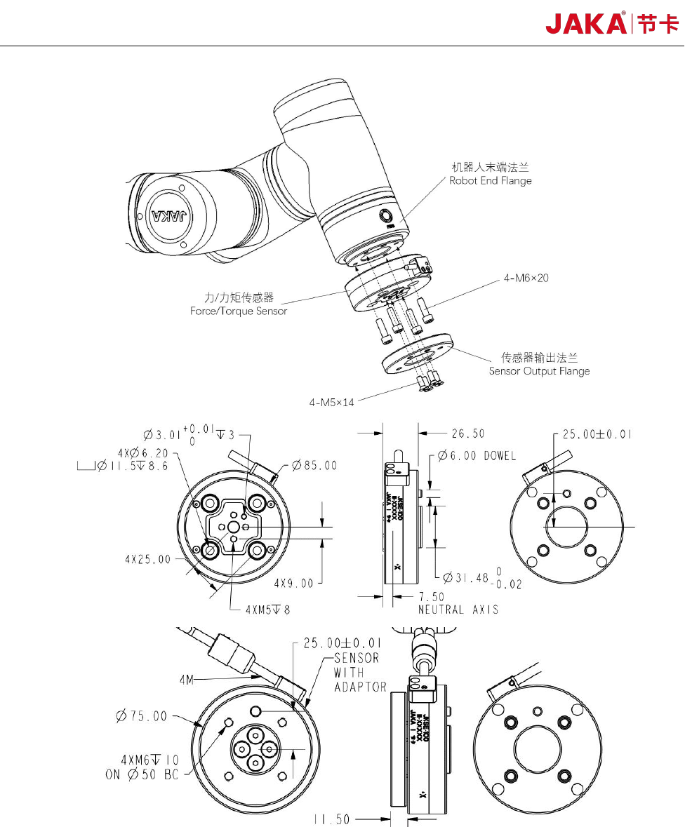
1.2 Sensor Installation
The sensor size, location of the fixed side (robot side) and the loading side (tool side) are
installed as shown in the figure below. The wire or joint is fixed at the fixed side to prevent the swing
or pull of the wire from affecting the measurement of the force sensor. The fixed side must be fixed
and external force is loaded from the loading side.
26 JAKA Zu Se
Sensor Installation
To tighten the screws, please tighten them gradually in the diagonal sequence. to make uniform
contact between the sensor and the equipment to be installed or the transfer fixture.
a. Before installation, please check that there is no damage or foreign matter on the surface of
the installation device and sensor. If the contact is not uniform due to foreign matters and other
JAKA Zu Se 27
factors, a gap will be formed between the equipment (or adaptor board) to be installed, which cannot
guarantee the IP64 performance of the product and will impact the output effect of the actual sensor.
b. The alignment pin is used to obtain repeatability of the equipment installation and connection.
If the locating pin is not used, the sensor performance will not be affected.
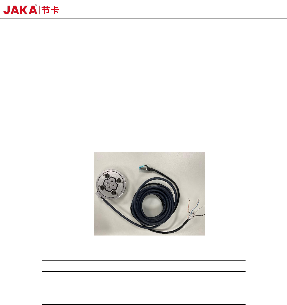
c. The connection cable is delivered with the product. The connection cable is a multi-core
cable with interfaces matching the cable interface on the sensor. As shown in the figure below, the
power is supplied by DC 24V. If the positive and negative poles of the power supply are connected
in reverse, the sensor will be damaged. Please be careful. The default IP of the sensor is
192.168.2.108. If you need to change it, please refer to the sensor III configuration instructions or
contact us. Connect the network port to the robot controller under the same network segment.
Cable Connection Operation
No.
Core color
Definition
1
Blue
Power supply+
2
White blue
Power supply –
3
Black
Shield line
1.3 Precautions for use
a. Do not use in an environment with temperature and humidity outside the allowed range of
specifications.
b. The wiring must be completely correct. When the power is turned on, please check whether
the color of the connecting cable is correct in accordance with this manual.
If an error occurs at the connection terminal, the internal circuit of the sensor may be short cut
and possibly be damaged. Please be sure to check.
c. The sensor contains an embedded system and other precision parts, please pay attention to