JAKA Zu se使用手册 - 英文版.pdf - 第5页
JAKA Zu Se 5 Chapter 2 Product D escription The JAKA Zu se system includes an APP, a robot, a control cabinet, and a force-sensing sensor device. As shown in Figure 2, the force-sensing sensor and the robot e nd flange a…
4 JAKA Zu Se
Chapter 1 Instruction
1.1 Background
As labor costs continue to increase, 3C, medicine, food, logistics and other industries have
begun to seek robot automation solutions. These emerging industries are characterized by a wide
variety of products, rapid update and iteration, and high flexible requirements for operators. In order
to realize robots working side by side with humans, it is necessary to improve the perception ability
of the robot body, so the sense of robot manpower arises at the right moment.
1.2 Purpose
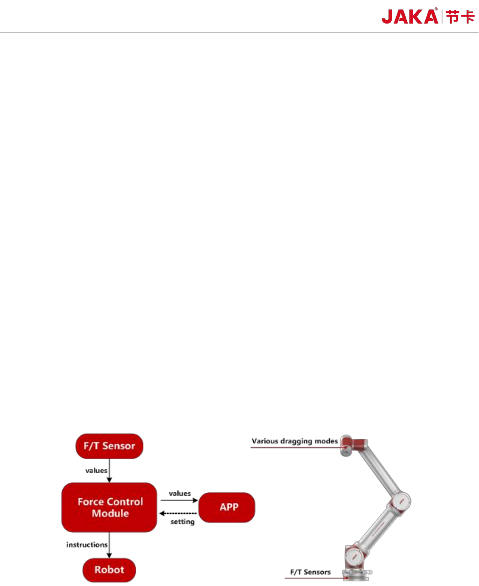
This product aims to adopt industry-level force sense sensor and integrate force control
algorithm with independent intellectual property rights, improve the perception ability of
collaborative robot ontology, and provide better human-computer interaction experience for
customers. As shown in Figure 1, the force sense
sensor
is installed on the robot side flange and the
force value is transmitted to the controller in real time. When the robot side actuator receives external
force, the posture of the end can be adjusted to adapt to the external force value. At the same time,
the customer can drag the position and posture of the robot from the robot side more smoothly.
Figure 1 JAKA Zu Se Functional Diagram
JAKA Zu Se 5
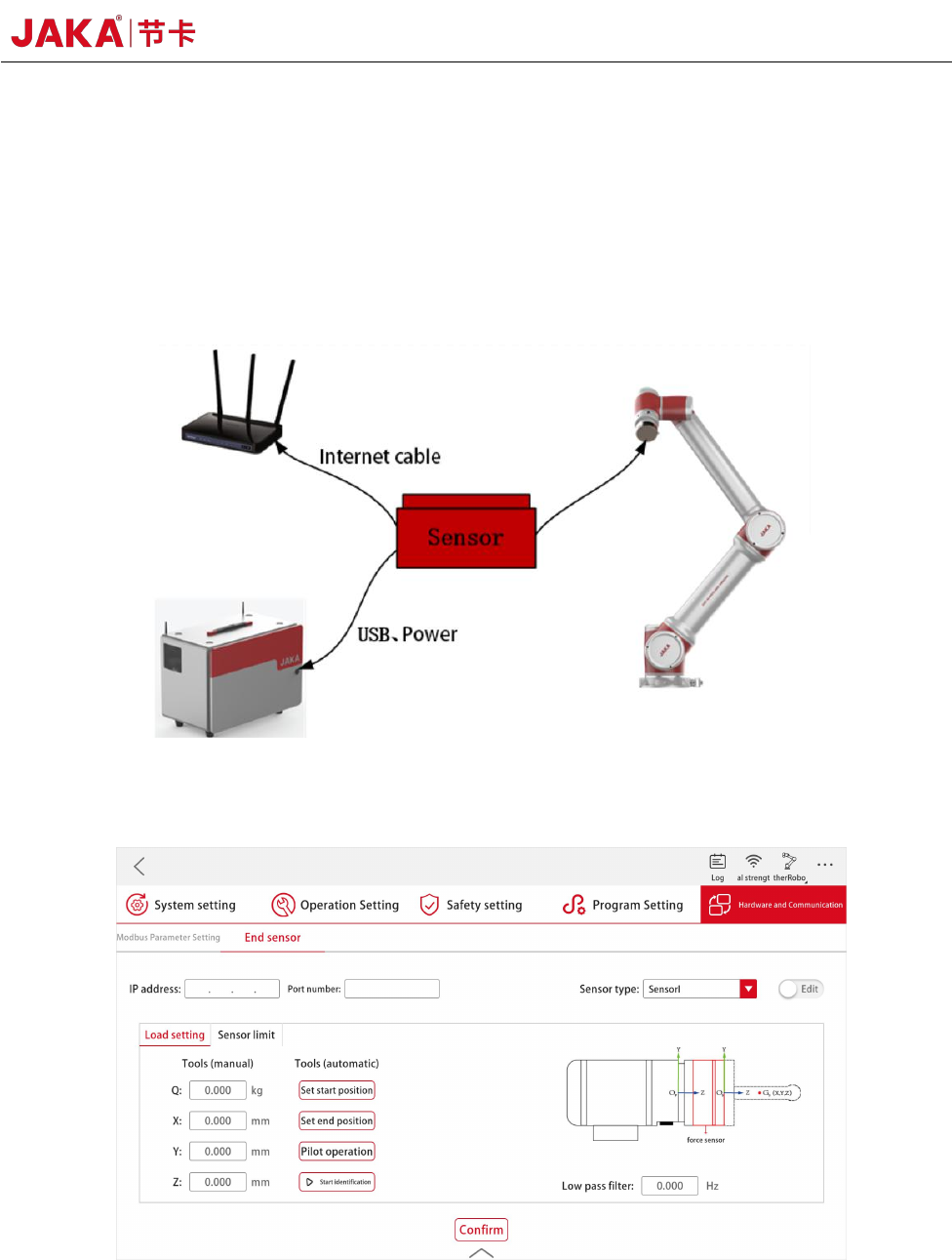
Chapter 2 Product Description
The JAKA Zu se system includes an APP, a robot, a control cabinet, and a force-sensing sensor
device. As shown in Figure 2, the force-sensing sensor and the robot end flange are mechanically
connected. The operation on the software is realized through the force sensor module in JAKA Zu
APP, as shown in Figure 3.
Figure 2 JAKA Zu Se System Diagram
Figure 3 APP Setting Interface of Force Sensor Module

6 JAKA Zu Se
Chapter 3 JAKA Zu Se System Construction
As shown in Figure 2 and 3, users need to complete simple hardware connection and software
settings to realize the setup of JAKA Zu se system. The specific setup process is as follows:
a. The user designs the connection between the force sensor and the end flange according to the
actual demand, and ensures that the X+ direction of the sensor is consistent with the X+ direction of
the robot flange through the connection or setting the tool coordinate system.
b. The force-sensing sensor can be powered by a robot controller or an additional 24V DC
power supply to the user. According to the different communication modes of the sensor, the sensor
can carry out serial communication through the USB interface connected to the control cabinet or
TCP communication through the network interface.
c. If sensor I or III is selected, IP and port number settings need to be made in the APP. Please
refer to the relevant sensor configuration appendix for specific setting methods. If sensor II is
selected, no IP and port number settings are required.