JAKA Zu se使用手册 - 英文版.pdf - 第19页
JAKA Zu Se 19 1.2 S ensor Install ation The sensor m ounting hole position and mounting dimensions are as foll ows. Sensor Size
18 JAKA Zu Se
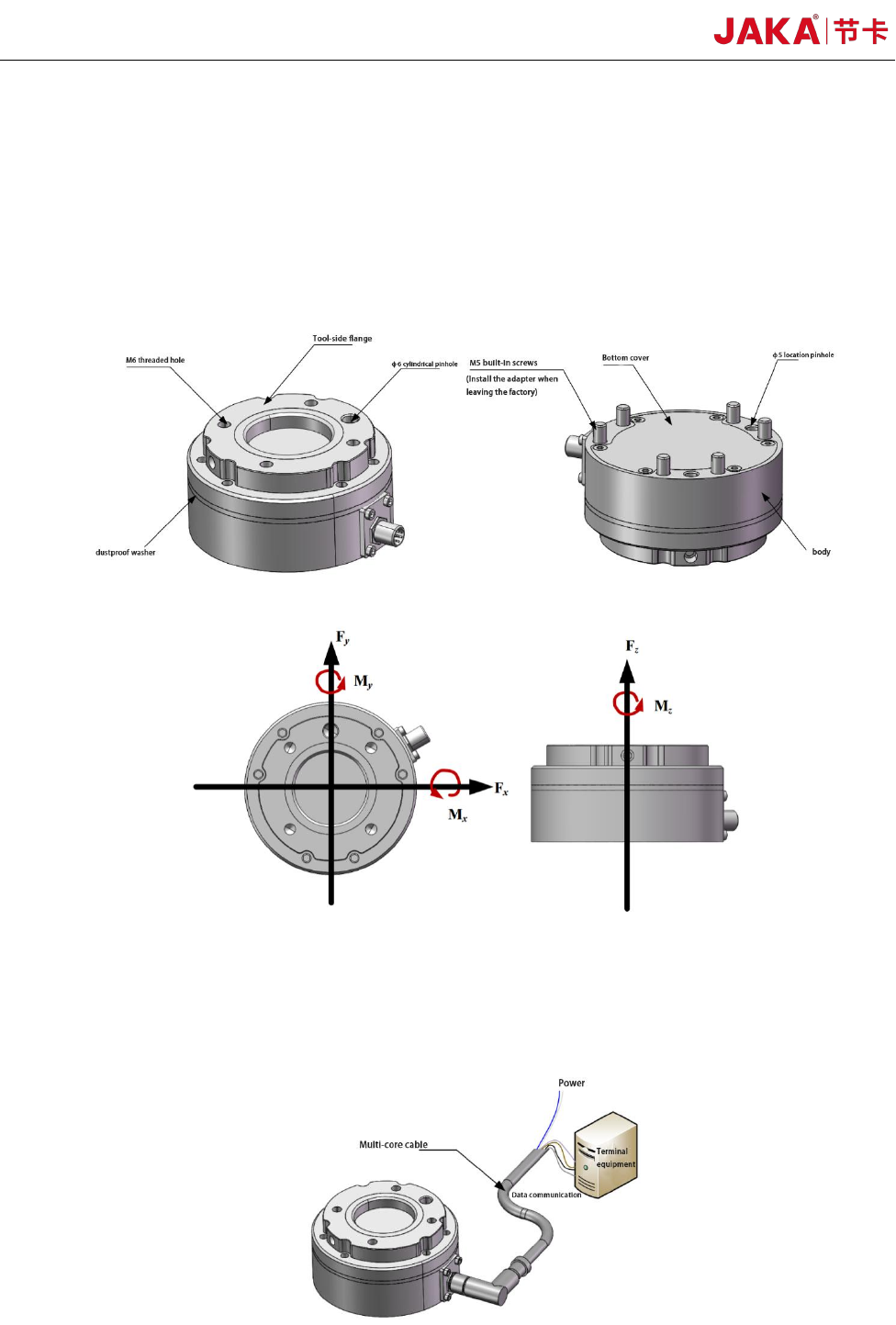
simultaneously. The sensor detects the relative deformation between the "Tool Side Flange" and the
"Body" caused by the applied force, and uses a resistance strain gauge to measure changes in the
sensor's elastic unit. The sensor contains an embedded system, which can collect and process the
signal changes of the resistance strain gauge in real time, and output the magnitude and direction of
the applied force in real time, with high precision and high response capability. When using the
sensor, please install it correctly avoid interference with the output result.
Sensor Appearance
Definition of the Sensor Coordinate System
The embedded acquisition system in the sensor body processes the voltage signal of the strain
gauge in real time, converts it into the actual load value, and outputs it in the form of digital signal.
Schematic Diagram of Electrical Connection of Sensor
JAKA Zu Se 19
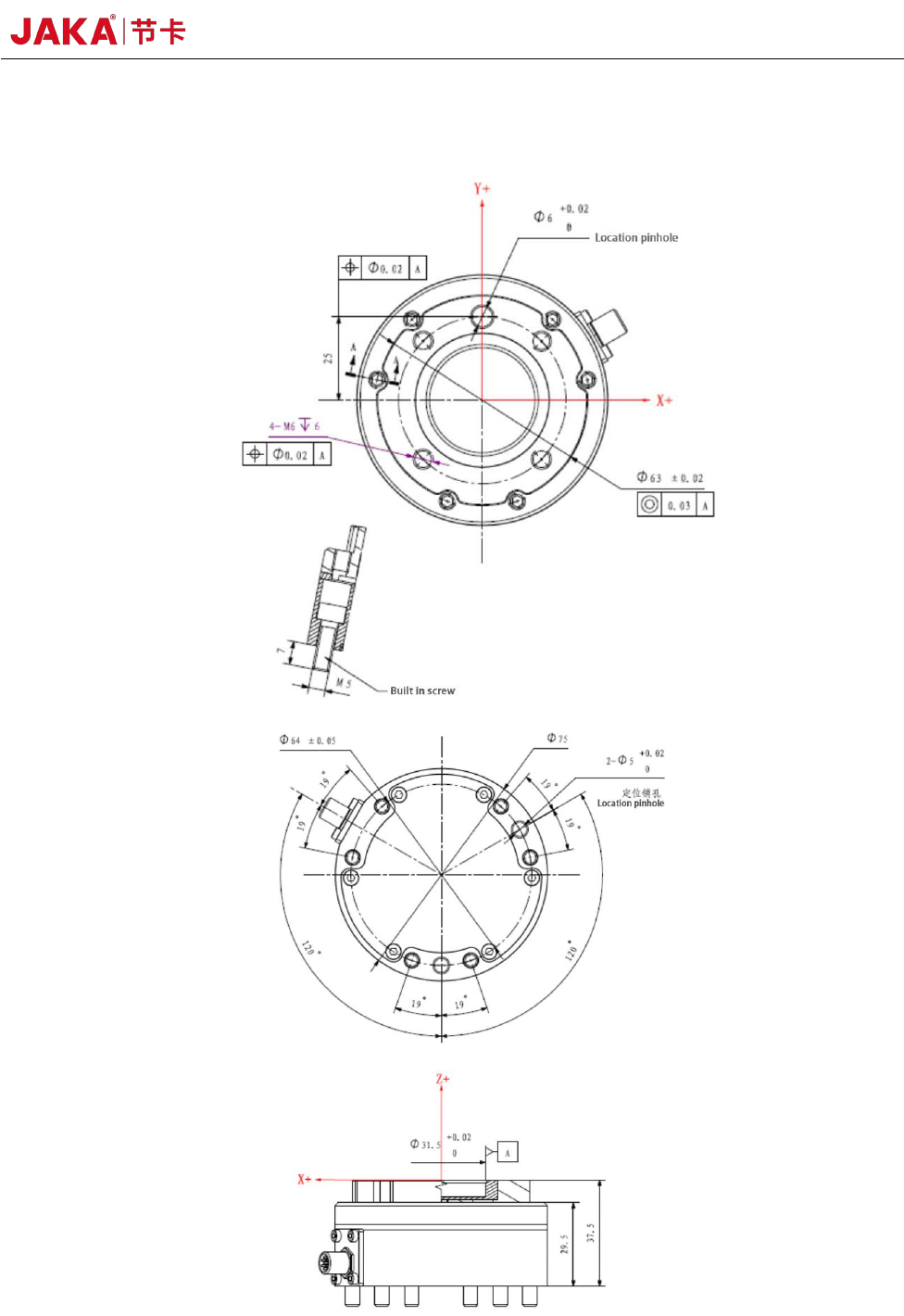
1.2 Sensor Installation
The sensor mounting hole position and mounting dimensions are as follows.
Sensor Size
20 JAKA Zu Se
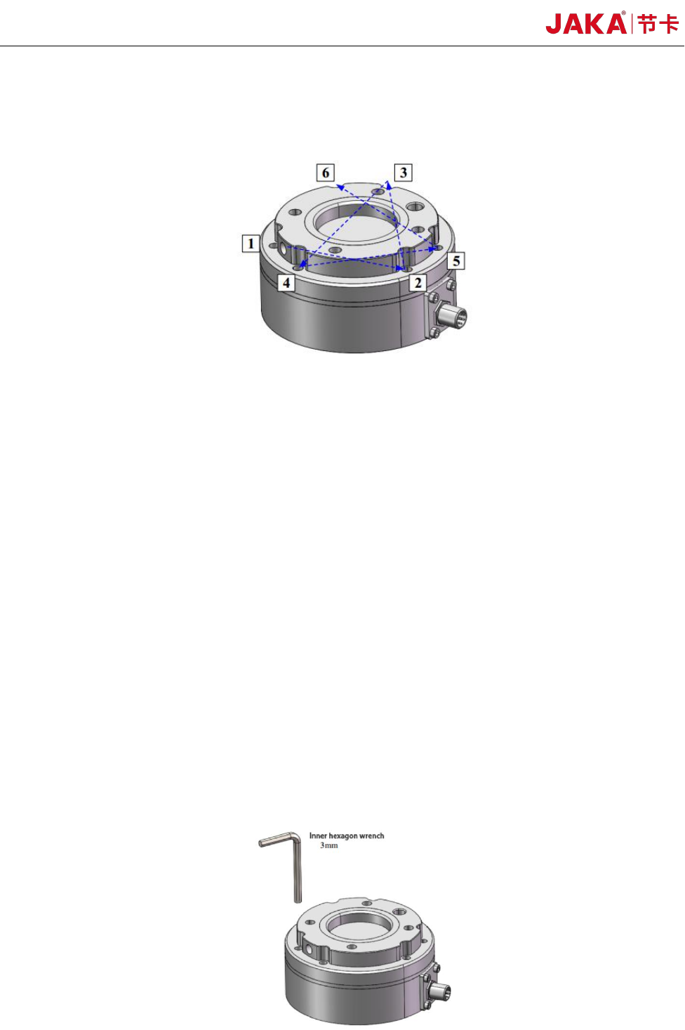
During tightening the bolts, please tighten the bolts gradually in the diagonal order as shown in
the figure to make uniform contact between the sensor and the equipment to be installed or the
transfer fixture.
Bolt Tightening Sequence
a. Before installation, please check that there is no damage or foreign matter on the surface of
installation equipment, adaptor plate and sensor. If the contact is not uniform due to foreign matters
and other factors, a gap will be formed between the equipment (or adaptor board) to be installed,
which cannot guarantee the IP64 performance of the product and will impact the output effect of the
actual sensor.
b. Separate the sensor from the adaptor plate and install the adaptor plate on the equipment to be
installed. When the sensor is delivered from the factory, the adaptor plate and the sensor body are
connected by 6 embedded hexangular bolts. Loosen 6 embedded hexagon socket bolts with 3mm
hexagon socket wrench and separate the adaptor plate from the sensor body. Use a φ6 alignment pin
to position the adaptor at the robotic arm end and the equipment to be installed. Use 2 M6 standard
hexagon socket bolts and 2 M6 non-standard hexagon socket bolts in the packaging accessories of
this product to fix the adaptor and the equipment to be installed. The alignment pin is used to obtain
repeatability of the equipment installation and connection. If the locating pin is not used, the sensor
performance will not be affected.